


ISM4 INSTALLATION & PROGRAMMING MANUAL
24
RS232 CONTROL AND PROGRAMMING
The
ISM4
can be controlled via
RS232
to allow power management of the devices controlled by the ISM4 from a
PC or appropriately capable system controller. It is important to note that the RS232 capability only allows for
Discrete ON/OFF
,
Toggle ON/OFF
as well as
Status
and
System Information
. The
RS232 Discrete ON/OFF
and
Toggle Commands
allow turning the
System Reference Device (Source 1) ON/OFF
. IT DOES NOT
ALLOW RS232 CONTROL OF ANY OTHER SOURCES OR FUNCTIONS.
The
Status
feature provides
queried
or
automatic feedback
of
Source ON/OFF Status
. Queried feedback will
provide
ON/OFF Status
of
Sources 1-4
in the form of
ASCII Text Strings
when asked by a control device.
Automatic Source Power State Notifications
are provided as
ASCII Text Strings
anytime there is a change in
Source ON/OFF Status
. This feature (Auto) can be turned on or off as appropriate for a given application. By
default, this feature is disabled.
ISM4 System Information
can also be queried for product information such as
Device
,
Hardware
and
Firmware
Rev
, should it be relevant in troubleshooting. Xantech Technical Support personnel may request this information
in a problematic application.
To respond to RS232 Commands, the ISM4 must be properly connected via the RS232 jack on the Rear Panel as
described in Section:
Other Connections/RS232
.
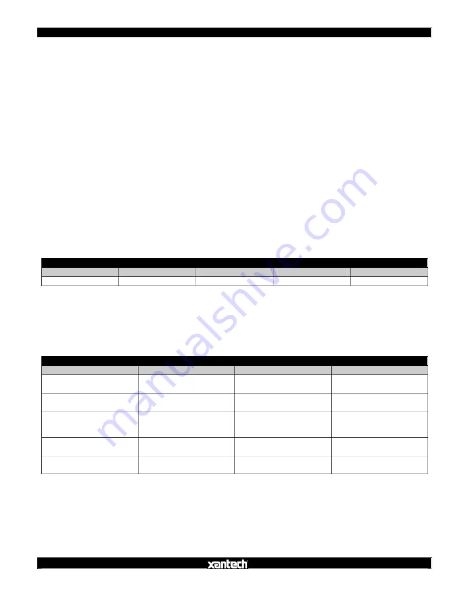
RS232 Com Port Settings
Use the following Table to configure the RS232 output of the device controlling the ISM4:
ISM4 RS232 COM PORT SETTINGS
Baud Rate
Parity
Data Bits
Stop Bits
Flow Control
9600 None 8
1 None
RS232 Command Strings
The following Table details the allowable
RS232 Command Strings
for control of the ISM4. Note only
Source 1
can be controlled for ON/OFF.
Automatic Source Power State Notification
is an optional feature that will
automatically
output a report any time there is a
change of state
on any
Sense Input
. The function can be
enabled/disabled using the Command Strings in the following Table. The actual report messages are detailed in
the
ISM4 Queries Table (Return)
.
ISM4 RS232 COMMAND STRINGS
Name
Command
Return
Remarks
Source 1 Discrete ON
!1PR1+
OK{CR}
ERROR{CR}
Turn Source 1 ON
Source 1 Discrete OFF
!1PR0+
OK{CR}
ERROR{CR}
Turn Source 1 OFF
Source 1 Toggle Power
!1PT+
OK{CR}
ERROR{CR}
Toggle Source 1 Power
(If OFF turn ON; If ON
turn OFF)
Enable Automatic Source
Power State Notification
1ZA1+ OK{CR}
ERROR{CR}
Enable Automatic Source
Power State Notification
Disable Automatic Source
Power State Notification
1ZA0+ OK{CR}
ERROR{CR}
Disable Automatic Source
Power State Notification
NOTE:
Allowable
Syntax for the Command Strings includes: (Source 1 Discrete ON used for example)
!1PR1+
!01PR1+
!1PR01+
!
ISM4 Queries
The ISM4 supports two layers of
Source Power Notifications
. The first is supported via explicit
RS232 Queries
(via the
Source Power Query
described in the
Queries Table
). The second is launched automatically by the