background image

System Operation 

Controller Operation           

820-0332


4-5 

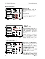
adjustment of Z height may be necessary after changing an ink cartridge, due to slight 

manufacturing variations between cartridges.  
The Z UP and Z DOWN buttons can also  be used to move the inker up or down by 

depressing and holding down either button.  This function is useful to quickly raise inker 

Z height when changing cartridges, but great care should be taken not to “run” the inker 

down into the wafer surface in this mode. 


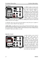
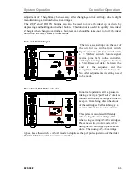
External Switch Input 

 There is a second input on the rear of 

the unit for use with a foot switch.  

Upon activation, the foot switch sends 

a > 50mSec switch closure signal 

(across pins 1&3) to the controller, 

enabling an inking sequence. There is 

a 50-millisecond delay between the 

end of the sequence and the 

recognition of the next switch closure.  

No other adjustments or settings need 

to be made.   


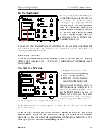
Rear Panel Puff Pulse Selector 

In normal operation, after a pause in 

inking activity, a “puff pulse” of air is 

introduced into the cartridge air line to 

keep ink from being drawn back out 

of the cartridge’s Teflon tubing by a 

vacuum effect, due to valve closure.  


This pulse is calculated differently 

when using the A4 cartridge, than 

when using existing A5-A8 cartridges.  

Place the switch in A4 mode when 

using the A4 cartridge to place small 

dots.  When using A5-A8 cartridge 

types, place the switch in A5-A8 mode to duplicate the puff pulse operation of the older 

350-0018 Motorized-Z pneumatic controller.  


Summary of Contents for 340-7110

Page 1: ...7110 and 340 7120 820 0332 Revision A September 2022 340 7110 Manual Micro Z Inker IMPORTANT OPERATION NOTICE The Model 350 0027 Micro Z Small Dot Pneumatic Controller has two 2 air inputs Each is de...

Page 2: ...s premtek com cn Website www premtek com tw Japan HUGLE ELECTRONICS INC 4 5 7 Iidabashi Chiyoda Ku Tokyo Japan 102 0072 Telephone 81 3 3263 6661 Fax 81 3 3263 6668 Email Xandex hugle co jp Website www...

Page 3: ...is designed to operate at 80 5 PSI FAILURE TO SET THE REGULATORS PROVIDING AIR TO THE CONTROLLER AT 80 PSI WILL RESULT IN INCONSISTENT SYSTEM OPERATION For more information contact Xandex Customer Ser...

Page 4: ...a practice that is not related to personal injury but may cause damage to equipment or property Use this product only in the manner described in this manual If the equipment is used in a manner not s...

Page 5: ...erate this product with a damaged DC power supply If the DC power supply is damaged in any manner replace it immediately A damaged DC power supply may result in user exposure to hazards The DC power s...

Page 6: ...n moving parts and eliminates potential vibration related parts movement for more accurate repeatable dot placement 4 An orifice has been added to the shuttle s air signal input tubing that acts to da...

Page 7: ...ion 4 1 Ink Cartridge 4 6 Cartridge Type Label Color Code 4 6 Ink Cartridge Labeling 4 7 Cartridge Preparation 4 8 Cartridge Installation 4 8 Cartridge Priming 4 10 Manual Micro Z Inker Assembly Setup...

Page 8: ...cifications 7 1 DC Power Supply Requirements 7 1 Pneumatic Controller Specifications 7 1 Inker Specifications 7 2 Ink Cartridge Specifications 7 3 Cartridge Availability 7 3 Dot Size Guidelines in Mil...

Page 9: ...cartridge barrel and forms a drop at the end of the needle tip When the shuttle is at its lowest position the drop makes contact with the wafer surface and forms a dot After several milliseconds the s...

Page 10: ...1 2 820 0332 This page is intentionally left blank...

Page 11: ...e 210 0113 Order Set 340 7110 05 Type P8 C for TEL 210 0120 Order Set 340 7110 04 Type J C for TSK Accretech 210 0114 Order Set 340 7110 03 Type C C for KLA 210 0110 Order Set 340 7110 02 Type A C for...

Page 12: ...3 Order Set 340 7120 05 Type P8 C for TEL 210 0120 Order Set 340 7120 04 Type J C for TSK Accretech 210 0114 Order Set 340 7120 03 Type C C for KLA 210 0110 Order Set 340 7120 02 Type A C for EG 210 0...

Page 13: ...ou are currently using another inker remove it from the prober equipment Move the chuck wafer from underneath the inker when installing inker to prevent damage 2 Install the inker base onto the prober...

Page 14: ...ion for ink cartridge installation inker setup alignment and controller operation instructions Do not install an ink cartridge on the inker until after the inker is installed on the prober or damage t...

Page 15: ...assembly by removing the plastic retaining nut Mount the regulator filter bracket in a convenient location mounting screws are not supplied Re mount the regulator to the bracket with the supplied nut...

Page 16: ...ents pull up on the knob on the top of the regulator to unlock then rotate the knob clockwise to increase or counterclockwise to decrease Push down on the knob after adjustment to lock it into positio...

Page 17: ...lied by Xandex is 3 feet 91 44 cm long The length of this air hose is a critical design specification If a longer air hose is required consult Xandex Product Support for mitigation information CONNECT...

Page 18: ...Controller Installation Installation 3 6 820 0332 This page is intentionally left blank...

Page 19: ...und when the programmed limit is exceeded For example if you select 30 000 dots turning the DOTS X 1000 thumbwheel to 30 the STATUS LED will light when 30 000 dots have been deposited Upon installatio...

Page 20: ...s applied to the controller with the RESET button depressed Audible Alarm An audible alarm is activated along with the STATUS LED whenever the DOTS X 1000 thumbwheel setting has been reached The alarm...

Page 21: ...ating modes The following is a description of the functions of each switch position Top Mode Switch Positions SETUP Cartridge air valve disabled for A4 Z height setup RUN Normal Operation DISABLE Shut...

Page 22: ...he X7110 Manual Micro Z inker assembly Z STEP will move the inker s Z stage up or down in small steps when the Z UP and Z DOWN buttons are pressed MICRO Z STEP will change the Z STEP to 1 10 of normal...

Page 23: ...ure signal across pins 1 3 to the controller enabling an inking sequence There is a 50 millisecond delay between the end of the sequence and the recognition of the next switch closure No other adjustm...

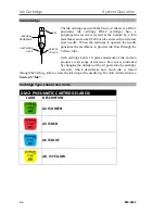
Page 24: ...to provide ink flow through the Teflon tube Each cartridge holds 1 0 grams minimum of ink and can produce a wide range of dot sizes Dot size is controlled by changing the duration of the air pulse int...

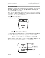
Page 25: ...will also void the cartridge warranty DieMark Cartridge Type Label This label contains the cartridge type either A4 A5 A6 or A8 DieMark Cartridge Expiration Date Label This label indicates the ink typ...

Page 26: ...l and remove cartridge The needle should be straight and the needle collar flush with the cartridge neck Do not shake the cartridge at any time as air bubbles may be introduced into the reservoir and...

Page 27: ...s clear of the cartridge needle tip after cartridge change out and priming 2 Never place hands or fingers under the cartridge needle 3 Keep hands and fingers clear of needle tip during cartridge chang...

Page 28: ...n is initially pushed the INK ON LED will begin to flash At the end of 3 seconds the INK ON LED will light continuously and the air valve will begin to pulse priming the cartridge Manual Micro Z Inker...

Page 29: ...drop is transferred to the wafer surface 7 Once the ink drop is released to the wafer surface run a test dot sequence to verify consistent transfer Fine Adjustments 8 If ink dots are consistent in siz...

Page 30: ...Note Due to the unavoidable incidence of slight manufacturing variations from cartridge to cartridge additional Z height adjustment of the inker may be necessary after changing ink cartridges 13 If th...

Page 31: ...d verify that the inker is at a safe Z height adjustment and position the chuck wafer under the inker and set the prober chuck Z Up If the inker height is adjusted with the prober stage Z Down the car...

Page 32: ...2 mil and then change to MICRO Z and adjust down for accurate placement Note The Z mechanism can become down loaded and must be backed off a thousandth or two to get accurate small increment downward...

Page 33: ...ll Xandex DieMark Ink Cartridges Cartridges are disposable and designed for single use only Using a refilled cartridge will have an adverse effect on functionality and performance Please note Xandex d...

Page 34: ...Cartridge Priming Tips System Operation 820 0332 4 16 This page is intentionally left blank...

Page 35: ...gh 6993 and 6997 are not contaminant controlled periodic test data indicates that these inks typically contain less than 100 ppm of Sodium Na and 400 ppm of Chloride Cl These levels are not certified...

Page 36: ...of 25 mil typically air dry to a hard cure in 45 minutes Dot sizes 25 mil may require significantly longer to cure An ambient cure time of up to 6 hours may be needed for larger dot sizes 8103 and 810...

Page 37: ...il 3 4 hours for 20 25 mil 4 10 hours for 25 40 mil Ink is permanent and may only be removed with great difficulty Hard Cure 150 Watt heat lamp at 5 6 inches OR oven at 110 150 C 5 10 minutes Ink is p...

Page 38: ...redients used are TSCA listed For an MSDS or more information on using DieMark Remover 8000 in your specific ink removal process contact Xandex Customer Service Ink Removal Procedure The following is...

Page 39: ...00 however Xandex does not guarantee that satisfactory results will be obtained None of the following solvents or ink removers are available from Xandex Aptek 6515 Ink Remover Markem 540 P 300 Resist...

Page 40: ...Ink Removal Information Ink 820 0332 5 6 This page is intentionally left blank...

Page 41: ...g 8103 and 8104 air dry glycol free inks should be used within 4 months or 3 days of cartridge opening 7824 and 7824T air dry ink within 4 months or 3 days after cartridge opening 2 Check for exposure...

Page 42: ...ressure too low Verify that or the controller s air regulators are set to 80 5 PSI 4 Z height adjustment is incorrect After cartridge replacement occasional Z height adjustment may be required due to...

Page 43: ...r is plugged into the controller 2 Verify that the Controller to shuttle air hose is not kinked clogged or pinched closed 3 Check Main Air pressure setting verify 80 5 PSI air input Unit functions nor...

Page 44: ...al Xandex distributor With the introduction of the Precision Shuttle in spring of 2022 shuttle maintenance has been dramatically simplified The new Precision Pneumatic Shuttle 316 0010 is standard on...

Page 45: ...rify input cable is plugged into the prober input on the Controller 2 Verify input cable is plugged into inker jack on prober 3 Check continuity of cable Replace repair if defective Unit powers up oka...

Page 46: ...e Thumbwheels 1 Verify that the air hoses from the controller to the inker are connected properly RED AIR HOSE connects to the ink cartridge BLUE AIR HOSE connects to the shuttle connection on the shu...

Page 47: ...Consumption per Regulator 80 PSI 5 PSI Instrument Air per ISA 7 3 specification 0 5 cfm 10 dots second Cycle Rate Exceeds 300 cycles minute Counters Eight Digit with External Reset Independent of Micr...

Page 48: ...branded electronic products with the WEEE Symbol to alert our customers that products bearing this label should not be disposed of in a landfill or with municipal or household waste in the EU Conform...

Page 49: ...conditions The information in this table is accurate as of the time of publication but is subject to change without notice Available standard cartridge and ink configuration 0 Not yet qualified by Xa...

Page 50: ...Mid 7 mil Mid 0 Mid 0 Mid 0 0 Max 10 mil Max 0 Max 0 Max 0 0 A5 Min 9 mil Min 16 mil Min 17 mil Min 9 mil 12 mil Mid 12 mil Mid 28 mil Mid 29 mil Mid 12 mil 23 mil Max 16 mil Max 32 mil Max 33 mil Ma...

Page 51: ...x 0 0 A5 Min 228 6 m Min 406 4 m Min 431 8 m Min 228 6 m 304 8 m Mid 304 8 m Mid 711 2 m Mid 736 6 m Mid 304 8 m 584 2 m Max 406 4 m Max 812 8 m Max 838 2 m Max 406 4 m 711 2 m A6 Min 203 2 m Min 508...

Page 52: ...Xandex assumes no liability for the advice given or results obtained Buyer expressly agrees that it will implement any advice thus given at its own risk and agrees to indemnify and hold Xandex harmles...

Page 53: ...nk signal cable 340 7110 05 X7121 Micro Z Motorized Pneumatic Inker Set EG 340 7120 01 X7122 Motorized Z Pneumatic Inker Set KLA 340 7120 02 X7123 Motorized Z Pneumatic Inker Set TSK 340 7120 03 X7124...

Page 54: ...02 Inker Assembly Micro Z Motorized Pneumatic 36 Air 320 7120 01 Inker Assembly Micro Z Motorized Pneumatic 60 Air 320 7120 02 Pneumatic Shuttle Precision Direct Mount 36 Air Hose 316 0010 Pneumatic...

Reviews: