background image

U

SER 

M

ANUAL


X

ORAYA

S

UITE


112 


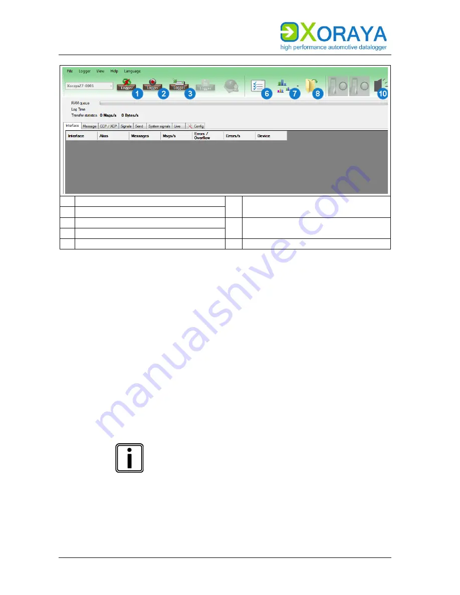
1  Release connection to logger 

8  Open the latest created session or 

measurement in the 

Viewer

 tool 

2  Start online logging 
3  Start Hdd logging 

10  Trigger acoustic signal to identify 

Minilogger Z7 

6  Display settings 
7  Displays the current bus traffic 


Use 

Display settings


(6)

 to customise the following: 


Path and filename (

 Export settings) 


Output format (

 Output formats) 


Acoustic warning or executing a script if a bus error is detected 


Buses to be recorded 


Colour assignments for the interfaces 


Signal description (

 Signal description settings) 


Load configuration template (Busspec) 


Manage logger favourites (

 Favourites) 

Store data on the PC: 


Click 

Start online logging


(2)


Data received via interfaces are recorded on the PC. 


HDD mode 

Start the recording on the internal or external storage 
medium of the X

ORAYA

 Z7 via 

Start Hdd logging


(3)

 or 

autonomously without a PC, as described in the relevant 
section. (

 HDD mode) 

Both modes can be operated simultaneously. 


Summary of Contents for XORAYA Z7

Page 1: ...User Manual XORAYA Z7 Edition 1 1 4 December 2018 ...

Page 2: ... of X2E GmbH Offenders shall be liable to pay compensation and may be subject to prosecution All product names and trademarks used in this manual are the property of their respective owners X2E GmbH Jahnstrasse 2b 76870 Kandel GERMANY Phone 49 7275 9143 200 Telefax 49 7275 9143 109 E Mail xoraya x2e de Internet http www x2e de Wiki http wiki x2e de ...

Page 3: ...ing 26 4 1 Unpacking 26 4 2 Selecting an installation location 26 4 3 Installing the XORAYA Z7 26 4 4 Installing the XORAYASuite 27 4 5 Connecting the XORAYA Z7 to the measuring environment 28 4 6 Connecting the XORAYA Z7 to the PC 31 5 XORAYASuite 32 5 1 Starting 32 5 2 Menu bar 33 5 3 Status bar 36 5 4 Connecting and disconnecting the XORAYA Z7 37 5 5 Configuration 40 5 6 Resetting to factory de...

Page 4: ...CONTENTS 4 7 Storage transport and disposal 170 7 1 Storage 170 7 2 Transport 170 7 3 Disposal 171 8 Appendix 172 8 1 Technical data 172 8 2 XORAYA Z7 pin assignments 173 8 3 Cable pin assignments 178 8 4 Output formats 184 ...

Page 5: ...afe proper and efficient operation of the XORAYA Z7 Following this user manual strictly helps in avoiding dangers reduces repair costs and downtime while increasing the reliability and service life of the XORAYA Z7 It should be read understood and applied by those using the XORAYA Z7 according to the user manual Pay particular attention to the safety section Safety and warranty the text warnings o...

Page 6: ...ent modifications Please ensure that you have the most complete and current XORAYA Z7 user manual Functions described herein correspond to the XORAYA Z7 current delivery state up to the development phase below Firmware version 4 09 xxxx XORAYASuite version 03 05 05 xx Please note that new features may not be described in full or described at all Users can change certain properties and functions vi...

Page 7: ...ing ALT Left arrow Text Housing label GUI element or other highlighting Placeholders for numbers 1 or A Reference to numbered markers in graphics 1 4 Pictograms This manual uses pictograms to highlight and ensure faster recognition of important or especially useful information Warning This type of symbols indicate warnings which must be observed The following subsections contain a description of t...

Page 8: ...rmation could result in injury or property and environmental damage WARNING This pictogram used in conjunction with the word Warning warns of a potentially imminent danger to the health and lives of people Ignoring this warning could cause serious personal injury including death in the worst case DANGER This pictogram used in conjunction with the word Danger warns of an imminent danger to the heal...

Page 9: ... provides the following information Latest software Latest firmware Latest licence file For access details please send an email stating your contact data to wiki x2e de We will send you the appropriate access data You may request your access details at any time if necessary ...

Page 10: ...e XORAYA Z7 is intended for use only by trained personnel The XORAYA Z7 must not be used in residential or living areas Its use is strictly limited to industrial environments The XORAYA Z7 must not be used in hazardous areas Always operate the XORAYA Z7 within its technical specifications Technical data The XORAYA Z7 may only be used under the conditions and for the purposes for which it was desig...

Page 11: ...nd burst tests the values for USB fall below minimal operating specifications because of its plug and play character Subsequently the USB device can be connected again and data traffic can be continued During ESD tests with a connected XORAYA external storage unit the XORAYA Z7 shuts down starts again automatically and continues logging in HDD mode Online logging has to be restarted manually via t...

Page 12: ...es Connected vehicles being operated on public roads bear an increased risk of injury and damage If available use configuration templates provided by the vehicle manufacturer Use preferably the passive recording modes of the interfaces CAUTION Device damage due to short circuit Bent connector pins pose a short circuit risk This can lead to abnormal behaviour or destruction of the XORAYA Z7 Likewis...

Page 13: ... damage due to pollution Avoid any contamination in plugs and sockets to ensure a reliable contact Keep the XORAYA Z7 clean CAUTION Device damage due to device opening Unauthorised opening of the XORAYA Z7 can lead to abnormal behaviour or destruction of the device Never open the XORAYA Z7 Contact X2E GmbH should maintenance and repairs be required CAUTION Device damage due to penetration of dust ...

Page 14: ... the power button on the front panel Pull the black plug connected to ground last when disconnecting the XORAYA Z7 from the power supply CAUTION Safety defects due to incorrect accessories and spare parts Accessories and spare parts that have not been recommended by X2E GmbH negatively affect the safety functionality and precision of the XORAYA Z7 X2E GmbH shall assume no responsibility whatsoever...

Page 15: ...pply The XORAYA Z7 is continuously developed The development process relies on the cooperation between the user and X2E GmbH 2 5 Warranty The warranty period is 12 months Device batteries whether internal or external are excluded from the warranty The warranty also excludes damages arising from improper handling X2E GmbH guarantees that the media on which the software is located are free of materi...

Page 16: ...the user X2E GmbH shall assume no liability for damages arising from faulty recorded data as well as damage due to incorrect configuration data entry and data transfer After configuring we recommend to verify the proper operation and plausibility of each sensor using some manual measurement over the entire measuring range X2E GmbH shall assume no further liability This limitation of liability also...

Page 17: ...and CAN FD FlexRay LIN RS 232 PSI5 Analog BroadR Reach MOST25 and MOST150 Ethernet 100Base T and 1000Base T GNLog and DLT via Ethernet and RS 232 CCP and XCP GPS The XORAYA Z7 based on the Xilinx Zynq 7000 All Programmable SoC is the new generation of the compact and inexpensive XORAYA datalogger The built in supercapacitor unit is able to bridge power fluctuations and to shut the XORAYA Z7 down s...

Page 18: ...on number for this XORAYA Z7 Configuration First block Product ID 0200 XORAYA Datalogger Second block Product variant 0300 XORAYA Z7 Third block Hardware revision DMF MOD Date of manufacture DMF and possibly of the last modification MOD Upon device specific issues always provide the serial number and configuration The interface configuration of a XORAYA Z7 is variable and therefore not recorded on...

Page 19: ...he delivery XORAYA Z7 with impact protection Power supply cable Software User manual Cable set depending on the interface configuration The following accessories are optionally available XORAYA external storage unit Power supply cable with AC adapter Additional cables Mounting material Device bag ...

Page 20: ...t in log interfaces H Service port C USB host port I USB device port D General status LEDs J Trigger wake button E LAN host ports K Power button F Port for external storage unit L Power trigger wake port Status LEDs of custom log interfaces A A constantly lit status LED indicates an existing and activated log interface on the corresponding slot The LED flashes when messages are received Status LED...

Page 21: ...te on the USB flash drive and copy the firmware archive there Connect the drive and the firmware is automatically updated Generating the supportfile The supportfile is a set of files that you can send to X2E support to help solve technical issues Create the folder xoraya_supportfile on the USB flash drive Connect the drive and the supportfile is automatically generated The Info LED flashes during ...

Page 22: ...irmware update or recovery mode Displays different error codes by flashing HDD Flashes when accessing the storage medium ext HDD Lights up when cable connection to XORAYA external storage unit is established Red connection enabled locked Green connection disabled via button unlocked LAN host ports E The XORAYA Z7 features four ports to connect to a switch or directly to a PC This is necessary to c...

Page 23: ... second before disconnecting the cable connection When the corresponding LED is lit green you can pull the cable Default button G Press the default button with a pointed object for at least 3 seconds to reset all XORAYA Z7 settings to factory defaults Service port H In case of errors this interface is used as a debugging interface by the X2E support team USB device port I This port has currently n...

Page 24: ... the XORAYA Z7 using this button when the device is connected to a PC and the Connect LED is lit In this case you can turn off the XORAYA Z7 via the Logger menu of the XORAYASuite Here you may choose between two options i e Shutdown and Shutdown no wake up Logger Power trigger wake port L By default the XORAYA Z7 must be supplied with 12 V DC voltage Optionally it can also operate with power suppl...

Page 25: ...aces are not terminated internally meaning that they are not equipped with termination resistors Custom log interfaces N The slots can be variably equipped with up to three additional interfaces Slot and channel number of each hardware interface are also displayed in multiple locations of the XORAYASuite tool Configuration Interface configuration Main overview for all interfaces Main overview for ...

Page 26: ...nent upon prompt notification Keep original packaging Keep the original packaging and packing materials for later storage or further transport 4 2 Selecting an installation location The XORAYA Z7 installation location must meet the following criteria Location of the DC power supply 12 V Distance of at least 2 cm to other devices Solid and stable base Adequate airflow XORAYA Z7 front and back sides...

Page 27: ...Microsoft Windows 8 32 Bit or 64 Bit Microsoft Windows 10 32 Bit or 64 Bit Hardware requirements Processor speed at least 1 GHz RAM at least 2 GB Storage space approx 120 MB available Software requirements Microsoft NET Framework Version 4 5 or higher Installation Close all open programs Use the XORAYASuite setup wizard from the supplied data medium or Download the latest version of the XORAYASuit...

Page 28: ...pin assignments Please note the port pin assignments when connecting the XORAYA Z7 with the measuring environment Wrong pin assignments lead to measurement errors Please note the following sequence Connect the data cables of all data buses to be monitored in the measuring environment Connect the data cables to the appropriate XORAYA Z7 ports Wherever possible tighten the connector screws on the XO...

Page 29: ... supply Using an incorrect power supply can lead to abnormal behaviour or destruction of the XORAYA Z7 Use only the supplied power cable Please ensure correct polarity upon connection Make sure that the power supply used meets the prescribed technical conditions Make sure that the power supply lies within permissible operating voltage of the XORAYA Z7 Please note the allowable voltage level when f...

Page 30: ...ply The XORAYA Z7 is securely connected to the measuring environment Once the supply voltage is established the XORAYA Z7 turns on and displays its operational status via the power button LED K CAUTION Damage due to improper device shutdown Disconnecting the power supply during operation may cause data loss and the destruction of the XORAYA Z7 Never disconnect the XORAYA Z7 from the power supply w...

Page 31: ...is configured using the main setting Automatically Switch Off Main Settings Users can wake up the XORAYA Z7 from sleep mode as follows Pressing the power button K Switching the power supply off and on Signal change from 0 V to 12 V at the trigger or wake input L Pressing the trigger wake button J Activity on a wakeable log interface 4 6 Connecting the XORAYA Z7 to the PC This section describes how...

Page 32: ...uration Customise the XORAYA Z7 behaviour Online Logging Start and stop logging Hdd Download Download measurements from the XORAYA Z7 storage medium Viewer Evaluate measurements Statistic Evaluate bus statistics Convert Convert log data to other formats Firmware Update Update firmware TK Commandline Command line access to the XORAYAToolkit The XORAYASuite is started Windows notification area Even ...

Page 33: ...rent interface configuration under a different name The subitem System settings and signals saves everything except the interface configuration Open Opens an info file DLI and the associated log data Alternatively ZIP archive containing info file and log data Close Closes the open log data Open SWU XSWU file Opens a firmware image Refresh properties Reloads the current configuration of a selected ...

Page 34: ...Customer default configuration Create Stores the current permanent configuration profile active in the customer default profile Customer default configuration Load Loads the customer default configuration profile into the active profile Reset configuration to factory settings Interfaces Resets the XORAYA Z7 interface configuration to factory defaults Reset configuration to factory settings System ...

Page 35: ...Adjusts the width of the columns in the Hdd Download tool to ensure all are visible simultaneously 1 Comment 22 Type spread Determines which tabs are shown in the Hdd Download tool Legend Determines whether the legend is shown in the Hdd Download tool This menu does not appear in the tools Viewer Convert and Firmware Update 5 2 4 Help Among other things you can use the Help menu to access this man...

Page 36: ...ir descriptions can be found in the corresponding sections of this user manual 5 3 Status bar The status bar on the bottom of the window provides information about the connected XORAYA Z7 for example the storage medium usage In addition the user interface is also adjustable for smaller displays there The following buttons do not appear in the tools Viewer Statistics and Convert 1 Show hide menu ba...

Page 37: ...YA Z7 1 Display available loggers 6 Display settings 2 Establish connection to logger Connect the XORAYA Z7 to the PC Connecting the XORAYA Z7 to the PC Turn on the XORAYA Z7 Start the desired XORAYASuite tool Starting Click Display available loggers 1 to start scanning for dataloggers Select the desired XORAYA Z7 using the assigned name Click Establish connection to logger 2 or In the Logger menu...

Page 38: ...onfiguration file You can edit a configuration file XML previously created without connecting to the XORAYA Z7 To do so select Offline Configuration in the drop down list Display available Loggers 1 in the Configuration tool 5 4 2 Disconnecting the XORAYA Z7 2 Release connection to logger 5 Display settings 3 Start Hdd logging Click Release connection to logger 2 or In the Logger menu click Discon...

Page 39: ... device from favourite list Save frequently used dataloggers in the favourites list Favourites are displayed first in the list of available dataloggers and are marked with the star symbol Add XORAYA Z7 manually Click Add a device to favourites manually 3 Specify Logger name and IP address Click OK Add XORAYA Z7 automatically Click Devices in the network 4 to start scanning for dataloggers Select t...

Page 40: ...the desired XORAYA Z7 Connecting the XORAYA Z7 The configuration can be performed WARNING Defects influencing the environment The incorrect XORAYA Z7 configuration can lead to the temporary delayed or permanent functional failure of connected vehicles Connected vehicles being operated on public roads bear an increased risk of injury and damage If available use configuration templates provided by t...

Page 41: ... sub items The current configuration of the selected sub item is displayed on the right side of the window This is where you can perform any changes required and optionally save them as a configuration file XML on your PC via button 6 The toolbar 7 allows a quick jump to all categories of this level Use the Default tab to access the screen for the main default settings Use the Properties tab to ac...

Page 42: ...figuration permanently The configuration is saved permanently Delayed change update For certain settings such as Name and IP Address changes are not applied immediately but only after a XORAYA Z7 restart The Maintenance symbol indicates whether there is a XORAYA Z7 malfunction and where appropriate the error source HDD mode Start the recording on the internal or external storage medium of the XORA...

Page 43: ...XORAYA Z7 These properties fall under various categories Main Settings Network Hard Disk Snapshot Versions Profile Select the category Click the root element of System Settings to display the main settings of all categories or Click a category to view the main settings of this category System Settings Main Settings ...

Page 44: ... the system time Automatically Switch Off Time period after which the XORAYA Z7 shuts down provided there is no connection to the XORAYASuite there is no activity on any interface for which Prevent Sleep Mode is activated Values Never 1 min 10 min 20 min 30 min 60 min 10 min Acoustic feedback Acoustic feedback when data recording is starting XORAYA Z7 is shutting down sleeping Off System Time Clic...

Page 45: ...USER MANUAL XORAYASUITE 45 System Settings Network 1 Open MAC IP assignments ...

Page 46: ...rver On or fixed IP Address On 0 0 0 0 Netmask Netmask that divides the IP address into network and host part 255 255 255 0 fixed IP Address XORAYA Z7 with static IP address Off Provided the check box is selected the XORAYA Z7 is only DHCP server if it cannot find another DHCP server within the network Otherwise the XORAYA Z7 requests the IP address from this server acting as DHCP client Static MA...

Page 47: ...tains the addresses of the PCs in the network Red exclamation marks flag PCs outside the IP range Special care in network settings Exercise extreme caution when changing these settings Under certain circumstances incorrect network settings of the XORAYA Z7 cannot be corrected In this case you should reset the XORAYA Z7 back to factory defaults by pressing the default button G for 3 seconds Connect...

Page 48: ...4 Remove external storage medium safely Only with connected XORAYA external storage unit These settings and displays refer to the currently active storage medium represented by the blue background colour If a XORAYA external storage unit is connected to port F you change the active storage medium via the buttons 2 and 3 Connections and controls ...

Page 49: ...rnal or external storage medium Off Disabled Loop Circular buffer which contains the most recent minutes of the recording Linear Ongoing Off Compression Compression reduces the data volume and as a result the download time because data are decompressed on the PC After selecting the check box Compression choose the compression method via the drop down list 1 ZIP slower higher compression rate LZ4 f...

Page 50: ...measurement Measurement data are processed as queues on the log interfaces In addition to the default queue for packet data the XORAYA Z7 is able to use the faster stream queue where Ethernet data are saved directly without creating statistics You can set snapshots for both queues separately Setting the snapshot Configure the snapshot of the desired queue Create one or multiple triggers for the ac...

Page 51: ...Trigger Post time Stream queue Trailing time of the snapshot for the stream queue in ms 0 Log mode Stream queue Snapshot recording mode for the stream queue Linear Ongoing Loop In a loop that is overwritten as the specified size is reached Linear Loop size Stream queue Factor determining the size of the loop in MB multiplied by a fixed predefined value 3 Interval Time range in ms during which mult...

Page 52: ...tion customer default a customer default configuration 1 Activate password protection Create customer default profile Enter customer default in the text box and click Create or In the Logger menu click Customer default configuration Create Load customer default profile Click Load in the row of the customer default profile or In the Logger menu click Customer default configuration Load or Press the...

Page 53: ...th enabled password protection you can still temporarily save settings and create profiles without needing to enter the password 1 Unlock password protection Unlock password protection for active profile Click Unlock password protection 1 In the newly opened window enter the correct Password Click OK The password protection is unlocked Reset password If you have forgotten your password you can res...

Page 54: ...load client settings onto the logger 2 Delete client settings from the logger Save settings on the XORAYA Z7 Specify the export settings Fehler Verweisquelle konnte nicht gefunden werden Specify the output formats Output formats selection Click Upload client settings onto the logger 1 The settings are temporarily or permanently saved on the XORAYA Z7 and can be loaded in the Hdd Download tool Rese...

Page 55: ...ANUAL XORAYASUITE 55 System Settings DLN Set up a Distributed Logging Network consisting of data sink master and one or multiple probes For further information see the quick manual for the XORAYA µT Z7 probe ...

Page 56: ...E 56 System Settings Versions All properties in this category are immutable and purely informative Among other things this displays version numbers for various XORAYA Z7 components as well as additionally activated licences ...

Page 57: ...outing Other Advanced Interface or channel selection Click the root element Interfaces to display the main settings of all interfaces or Click an interface to display the main settings for all channels of this interface or Click an interface channel to display the main settings for this channel Cross references to the interfaces CAN Analog DiagXCP FlexRay Ethernet Event LIN VIDEO Button RS 232 Dia...

Page 58: ...faces Double click a row in the table to jump directly to the corresponding interface or to the corresponding channel Reducing power consumption of the XORAYA Z7 To reduce the XORAYA Z7 power consumption disable all channels unneeded ...

Page 59: ...lt the FD specific settings are missing on the remaining channels CANFD_4PLUS_ For each of these licences the number of CAN FD capable channels is increased by 4 Check in category Versions of system settings to verify which licences are activated for your XORAYA Z7 Versions CAN Settings ...

Page 60: ...not go into sleep mode as long as there is activity on this channel On Wake XORAYA Z7 wakes up from sleep mode as soon as there is activity on this channel On Acknowledge Send Acknowledgment and transmission capacity Send and acknowledge XORAYA Z7 operates in active mode on the CAN bus transmission possible acknowledgment of CAN messages generation of error frames passive not send acknowledge XORA...

Page 61: ...USER MANUAL XORAYASUITE 61 CAN Trigger 1 Number of bytes for the trigger 3 Number of bytes for the response 2 8 byte blocks of the trigger 4 Byte values of the response ...

Page 62: ...er Id specify the ID of the CAN message that raises a trigger Changing the numbering system Select the check boxes Extended Frame Can FD and Bit Rate Switch as desired Specify the Number of bytes for the trigger 1 Select one of the 8 byte blocks of the trigger 2 for editing Specify the bytes of this payload block Set bits Specify further 8 byte blocks of this trigger Repeat as necessary for up to ...

Page 63: ...xes Extended Frame Can FD and Bit Rate Switch as desired Specify the Number of bytes for the response 3 Specify the Byte values of the response 4 Repeat as necessary to configure a second trigger response CAN trigger responses Trigger responses are only sent if the setting Acknowledge Send is not set to passive not send acknowledge To test the transmission of a CAN response click the corresponding...

Page 64: ...d routing 1 Under Source interface choose the receiving CAN channel Under Source msg ID specify the ID of the source message Changing the numbering system Select the check box Ext ID for a 29 bit ID instead of a 11 bit ID Optional Under Target msg ID specify content and length of the target message ID If you do not specify a target message ID the source message ID is applied Click Save routing 3 R...

Page 65: ...es contain signals which hold the specific values General system statistics are for example RAM queue fill level CPU load Storage medium usage Interface statistics Transfer speed in kB s Messages per second Overflow counter Error counter Setting Description Default Enable Enable interface statistic over CAN messages Off Offset User defined ID offset of the sent statistic messages 0 ...

Page 66: ...e ID in orange is reserved and is automatically adjusted for each interface channel by the software Click the DBC button to open the generated messages and signals as a DBC file in a text editor and to save them for later analysis Restriction of statistic over CAN Statistic over CAN messages can only be activated on one CAN channel at the same time ...

Page 67: ...figuration template provided by the vehicle manufacturer Off Prevent Sleep Mode XORAYA Z7 will not go into sleep mode as long as there is activity on this channel On Wake XORAYA Z7 wakes up from sleep mode as soon as there is activity on this channel On Allow sending Allow sending on this channel requirement for XCP on FlexRay Additionally a FIBEX file is required Off MFR config Fibex file Path an...

Page 68: ...er rate in bit s Values 20000 19200 9600 4800 2400 19200 Use Busspec Load configuration template provided by the vehicle manufacturer Off Prevent Sleep Mode Datalogger will not go into sleep mode as long as there is activity on this channel On Wake Datalogger wakes up from sleep mode as soon as there is activity on this channel On Show no slave response as error Show error if slave is not respondi...

Page 69: ...der Id specify the ID of the LIN message that raises a trigger Changing the numbering system Specify the payload bytes from 1 to 8 Set bits Repeat as necessary for up to a total of five triggers No trigger response Because of the missing transmission capability there are no trigger responses available for the LIN interface ...

Page 70: ...USER MANUAL XORAYASUITE 70 RS 232 ...

Page 71: ... data bits of a data block Values 5 bit 6 bit 7 bit 8 bit 8 bit Parity Parity check for error detection Values None Odd Even None Stopbits Number of stop bits that mark the end of a data block Values 1 bit 2 bit 1 bit keep low level data stream Underlying RS 232 data are saved Off Message Delimiter Delimiter that marks the end of a message Values LF 10 0x0A end of line None LF 10 0x0A Max packet s...

Page 72: ...SER MANUAL XORAYASUITE 72 Analog Analog Common Settings Setting Description Default Sample Rate Samples per second Applies to all channels of the interface 10 Enable Turn on logging for this channel Off ...

Page 73: ...ed by the vehicle manufacturer Off for CAN bus Configuration template for the CAN bus Analog data are converted to CAN for further processing by CARMEN Sample Rate Samples per second Applies to all channels of the interface Button Edit opens the common settings 10 Divider Divisor of the sampling rate Applies separately for each channel 1 Threshold Threshold of voltage change needed to initiate dat...

Page 74: ...ing for this channel On Alias Freely selectable channel name ethernet Bus ID Additional ID for subsequent evaluation Use Busspec Load configuration template provided by the vehicle manufacturer Off Prevent Sleep Mode XORAYA Z7 will not go into sleep mode as long as there is activity on this channel On ...

Page 75: ...ueue dispatching filter EtherType and VLAN Configure pre filters Click Add pre filter 1 Choose the Filter type only MAC is available at the current development stage Under Direction choose if the filter applies to a participant who is Source Destination or both Under Operator choose if the filter is added to the whitelist or the blacklist Specify the MAC address Click Save pre filter 3 Repeat as n...

Page 76: ...f the Ethernet frame contains no or only one VLAN tag the filter conditions for the non existing fields are ignored Via Load presets you can configure filter conditions in such way that either all frames are assigned to streaming data Streaming logging only or all frames to packet data Packet logging only Setting Description Default EtherType Expected result of the check on the EtherType field if ...

Page 77: ...USER MANUAL XORAYASUITE 77 Ethernet protocols In this configuration section you can add update and delete GNLog and DLT channels ...

Page 78: ...revent Sleep Mode XORAYA Z7 will not go into sleep mode as long as there is activity on this channel On Debug level Detail level of the debug information GNLog 0 to 3 max DLT 0 None to 6 Verbose GNLog 2 DLT 0 None Trace state Send trace messages Off Verbose mode Off Send only dynamic data On Send dynamic and static data Off VLan Id Check box activates VLAN ID according to IEEE 802 1Q Values 1 to 4...

Page 79: ...s Check in category Versions of system settings to verify which licences are activated for your XORAYA Z7 Versions VIDEO Settings Setting Description Default Enable Turn on logging for this channel Off Alias Freely selectable channel name video Bus ID Text box Bus ID Additional ID for subsequent evaluation URL To control an IP camera default enters the sample configuration of a Basler camera Preve...

Page 80: ...st 3 min is saved permanently video screenshot Create screenshot video startStream Start video stream video stopStream Stop video stream Configure triggers On the header of the desired trigger action click Add trigger 1 Select the desired Trigger type 2 Create a single condition or multiple combined conditions for this trigger Create trigger conditions If required repeat the above steps for furthe...

Page 81: ...UAL XORAYASUITE 81 DiagCCP DiagCCP Settings 1 Clear all settings 5 Open selection file 2 Edit CAN interface channel 6 Settings 3 Open A2L file 7 Traffic light for the bus load 4 Traffic light for the EPK check ...

Page 82: ...as long as there is activity on this channel Off Source Physical CAN channel to be used Can_1 can1 A2L file Description file which is suitable for the ECU and is loaded to configure the CCP connection Selection file Signal filter file XML CFG or LAB which contains a pre selection of the signals to be monitored Retry max Maximum number of retries after unsuccessful connection attempt 3 Data timeout...

Page 83: ...els of the Traffic light for the EPK check 4 green check successful yellow check not possible red check not successful Signal configuration Click Open selection file 5 and select a suitable XML CFG or LAB file or Click Signal selection and select the signals manually Filter The XORAYASuite calculates the expected percentage of the bus load increase The result evaluation is displayed via the Traffi...

Page 84: ...event channel column or Highlight one or multiple rows and right click to activate these signals simultaneously for one event channel Select signals for the polling measurement mode Click Add polling channel 9 The button is inactive if the A2L file does not support polling In the row of the signal select the polling cycle from the drop down list Filter signal list Enter the term or partial term in...

Page 85: ...ptionally encrypted on the XORAYA Z7 Other Status of the signal definition file 10 displays the current state of the file and changes its state by clicking not generated saved on XORAYA Z7 saved encrypted on XORAYA Z7 not saved on XORAYA Z7 If supported by the A2L file you can reduce the sampling rate of each event channel by increasing the Prescaler 11 ...

Page 86: ...not create trigger conditions the CCP recording provided it is activated starts and stops automatically at the beginning or ending of the data recording in online mode or HDD mode Configure triggers On the header of the desired trigger action click Add trigger 1 Select the desired Trigger type 2 Create a single condition or multiple combined conditions for this trigger Create trigger conditions If...

Page 87: ...a reduced A2L file and save it optionally encrypted on the XORAYA Z7 Create and encrypt the signal definition file by selecting the check boxes under MDF Export of signals Add additional signals 4 to the signal definition file by selecting the desired signals 5 Signal selection By clicking 1 you also display the signals which are imported from the A2L file By clicking 2 you delete the selected sig...

Page 88: ...ion of a seed and key function for the encrypted communication with the ECU Create and test the seed and key function Click Add basic structure of the function 1 Insert the algorithm that corresponds with the ECU Define the Input data 2 to test the function Click Execute function 3 The XORAYASuite calculates the output data key from the input data seed and compares it with the key calculated by th...

Page 89: ...P DiagXCP Settings 1 Clear all settings 5 Open selection file 2 Edit interface channel 6 Settings 3 Open A2L file 7 Traffic light for the bus load 4 Traffic light for the EPK check 8 Engine RPM Only for angle synchronous event channels ...

Page 90: ...reely selectable channel name xcp Bus ID Additional ID for subsequent evaluation Prevent Sleep Mode Datalogger will not go into sleep mode as long as there is activity on this channel Off Source Physical CAN or FlexRay channel to be used Can_1 can1 A2L file Description file which is suitable for the ECU and is loaded to configure the XCP connection Transport layer Selection if the A2L contains mul...

Page 91: ... 6 is activated Alias is also changed If the A2L contains multiple transport layer descriptions select the layer from the appearing window You can change this selection afterwards via the drop down list Transport layer If the time value T7 is equal to 0 increase this value in the appearing window to avoid protocol errors with the ECU You can change this value and all the other time values in the c...

Page 92: ...ion is displayed via the Traffic light for the bus load 7 If angle synchronous RPM dependent event channels are used select the Engine RPM 8 which influences the bus load calculation Configure the levels of the Traffic light for the bus load 7 Right click on the traffic light and then on Edit traffic light settings for this interface type Specify the percentage limit between green and yellow stand...

Page 93: ...row for the event channel column or Highlight one or multiple rows and right click to activate these signals simultaneously for one event channel Select signals for the polling measurement mode Click Add polling channel 9 The button is inactive if the A2L file does not support polling In the row of the signal select the polling cycle from the drop down list Filter signal list Enter the term or par...

Page 94: ...er Status of the signal definition file 10 displays the current state of the file and changes its state by clicking not generated saved on XORAYA Z7 saved encrypted on XORAYA Z7 not saved on XORAYA Z7 If supported by the A2L file you can reduce the sampling rate of each event channel by increasing the Prescaler 11 The column order of the event channels is adjustable via the drop down lists 12 ...

Page 95: ...not create trigger conditions the XCP recording provided it is activated starts and stops automatically at the beginning or ending of the data recording in online mode or HDD mode Configure triggers On the header of the desired trigger action click Add trigger 1 Select the desired Trigger type 2 Create a single condition or multiple combined conditions for this trigger Create trigger conditions If...

Page 96: ...a reduced A2L file and save it optionally encrypted on the XORAYA Z7 Create and encrypt the signal definition file by selecting the check boxes under MDF Export of signals Add additional signals 4 to the signal definition file by selecting the desired signals 5 Signal selection By clicking 1 you also display the signals which are imported from the A2L file By clicking 2 you delete the selected sig...

Page 97: ...ta This category consists of the following elements Overview of the configured event channels Timeout values changeable FlexRay buffer configuration partly changeable Mapping of the FlexRay buffers to the event channels changeable Definition of a seed and key function for the encrypted communication with the ECU ...

Page 98: ...d basic structure of the function 1 Insert the algorithm that corresponds with the ECU Define the Input data 2 to test the function Click Execute function 3 The XORAYASuite calculates the output data key from the input data seed and compares it with the key calculated by the ECU ...

Page 99: ...shots the Button interface Event Settings Setting Description Default Enable Turn on logging for this channel On Alias Freely selectable channel name event Bus ID Additional ID for subsequent evaluation Prevent Sleep Mode XORAYA Z7 will not go into sleep mode as long as there is activity on this channel On ...

Page 100: ...igger conditions that write custom event messages Configure triggers Click Add trigger 1 Select the desired Trigger type 2 Create a single condition or multiple combined conditions for this trigger Create trigger conditions If required repeat the above steps for further triggers Number of configurable triggers You can configure a maximum of ten event triggers ...

Page 101: ...ggered by the following trigger types Each trigger type is assigned a channel of the button interface as follows Connections and controls trigger_button Pressing the trigger button J wake_line Signal at the trigger input L Actions with a yellow background and a blue outline are enabled ...

Page 102: ...ep mode as soon as there is activity on this channel On Debounce time Bridging time in µs to prevent undesired multiple events when a trigger is raised 1000 Action 1 Start logging On Action 2 Stop logging Long press is required at least 3 s On Action 3 Create snapshot Off Action 4 Eject USB device Long press is required at least 3 s Off Action 5 No function for the XORAYA Z7 Off Action 6 No functi...

Page 103: ...ames for easier handling Settings 1 Add signal manually 4 Refresh signals 2 Edit signal 5 Configured signals 3 Delete signal 6 Signal selection Select the desired signals from 6 to add them to the list of configured signals 5 Signal selection This list is stored temporarily or permanently on the XORAYA Z7 Click 1 or right click anywhere in the list 5 to add additional signals manually Click 2 or r...

Page 104: ... of system settings to verify which licences are activated for your XORAYA Z7 Versions Add signal processing Click Add signal processing 2 Select the desired signal processing type The following signal processing types are available Log Only recording no binning Count Signal binning Compound Combined binning of two signals Signal binning Classes reflect signal value ranges Classification or binnin...

Page 105: ...ecify the Interval Click Save signal processing 1 The log signal processing is stored on the XORAYA Z7 Interval of the log signal processing If you specify an interval the last measured value of the signal is counted in this time range If you do not set an interval corresponding to a 0 in the text box the value of the signal is stored on each occurrence ...

Page 106: ...ve text boxes i e Number of classes Begin End Width and Span width you would like to specify or Select Automatic to create classes of constant width uniformly over the entire value range Complete all active text boxes in the Calculation tab The XORAYASuite calculates the remaining values and fills the text boxes accordingly Specify the Interval Click Save signal processing 1 The count signal proce...

Page 107: ...l signal processing 4 Signal 2 The compound signal processing corresponds to a combined count signal processing for two signals and is processed by the XORAYASuite as a two dimensional matrix Therefore the total class count is a product of the number of classes for both signals Add compound signal processing Configure the binning for the first signal 3 Configure the binning for the second signal 4...

Page 108: ...rocessing 2 Delete signal processing Edit signal processing Select the signal processing in the list 1 Click Edit signal processing 3 or Right click the signal processing and then click Edit signal processing Delete signal processing Select the signal processing in the list 1 Click Delete signal processing 2 ...

Page 109: ... Z7 wake up on bus activity is not possible logger shutdown_wakeup Shut down XORAYA Z7 wake up on bus activity is possible logger snapshot Trigger snapshot Snapshot Add trigger On the header of the desired trigger action click Add trigger 1 Select the desired Trigger type 2 Create a single condition or multiple combined conditions for this trigger Create trigger conditions If required repeat the a...

Page 110: ...figuration or one or all interfaces to their factory defaults or Press the default button G for at least 3 seconds to reset all XORAYA Z7 settings Connections and controls The XORAYA Z7 goes into idle state by way of confirmation The configuration is reset Updating the firmware Factory setting are automatically restored whenever features are added or eliminated upon a firmware update Firmware Upda...

Page 111: ...is case as the XORAYA Z7 is fully autonomous in this mode HDD logging may still be started and stopped from the PC Simultaneous recording modes Both modes can be operated in parallel but separately controlled 5 7 1 Online mode The Online Logging tool enables data recording in online mode Connect the XORAYA Z7 to the measurement environment Connecting the XORAYA Z7 to the measuring environment Conn...

Page 112: ...formats Acoustic warning or executing a script if a bus error is detected Buses to be recorded Colour assignments for the interfaces Signal description Signal description settings Load configuration template Busspec Manage logger favourites Favourites Store data on the PC Click Start online logging 2 Data received via interfaces are recorded on the PC HDD mode Start the recording on the internal o...

Page 113: ...ine logging 10 Trigger acoustic signal to identify Minilogger Z7 3 Start Hdd logging 5 Set Trigger for later evaluation Online logging information is distributed over several tabs The following table describes the general function of each tab and the options offered in the context menu when right clicking ...

Page 114: ...Signals Monitoring of defined signals Signal selection Context menu Show or hide columns Hide selected signals Save load and delete signal lists Send Send user defined CAN RS 232 or Ethernet UDP messages once or cyclically System signals Display of system signals core temperature for example as widgets Live Live view of the current recording where a row corresponds to a message Context menu Show o...

Page 115: ... column Timediff is displayed when you set the Timemasters on a particular record This column contains the time difference of each record to the Timemaster Represent data in graphical form Click Displays the current bus traffic 7 Choose among Bus statistics Message statistics and Interface statistics the desired source data for graphical output Graph View Stop data recording Click Stop online logg...

Page 116: ...t C Connections and controls Optionally Connect a XORAYA external storage unit to the corresponding port F Turn on the XORAYA Z7 Start the HDD recording by pressing the trigger button J on the XORAYA Z7 Data received via the interfaces are recorded Stop data recording Press the trigger button J for at least 3 seconds Configuration of trigger button The behaviour of the trigger button can be config...

Page 117: ...d Disk The session size exceeds the maximum size specified In this case the current session is closed and a new session for the current measurement starts Sessions are closed under the following conditions Recording is stopped manually The XORAYA Z7 goes into sleep mode The maximum size is exceeded Existing sessions and measurements on the storage medium can be displayed downloaded or deleted in t...

Page 118: ...s link This file contains information about the included log interfaces and references to the corresponding binary files File Format Meaning name dli ASCII Master file Contains information about log interfaces and references to the binary files name dlm Binary Meta file Contains index information for faster search within binary data name _0000 dlf name _0001 dlf Binary Binary file Contains recorde...

Page 119: ...d tool of the XORAYASuite Starting Connect to the desired XORAYA Z7 Connecting the XORAYA Z7 or Connect to a USB flash drive that contains recorded measurements or Connect to a directory on your PC that contains a measurement recorded via USB USB flash drive in list The connected USB flash drive is only available in the list if it is named XORAYALOG and contains the folder usb_queue The following ...

Page 120: ...ttings for example enable disable time groups or eject the USB flash drive automatically after disconnecting Colour assignments for the interfaces Manage logger favourites Favourites Change temporary download folder When downloading measurements that include a stream queue part by default the XORAYASuite saves data in the Windows temporary folder If there is not sufficient disk space available on ...

Page 121: ...it menu Select all or Select none Sessions and Measurements tabs Calendar tab Time range tab Sessions Measurements You can show and hide the Sessions tab in the settings Select the check boxes in the Selected column or Right click to access the advanced selection options in the context menu ...

Page 122: ...lick the single arrows d to jump one day or one week forward or backward Click the double arrows e to jump three days or three weeks forward or backward Click the graphical representation of a measurement f to select it or Click and drag to select all measurements in this time range Select with date entry Specify start date and start time g Specify end date and end time h or Enter the duration i C...

Page 123: ... c Use the arrows d optionally to apply the start date or to jump one day forward or backward Specify the end time e Click Apply f Limit the time range further by clicking and dragging inside the graphical representation g History The time ranges defined since starting the tool can be selected again via the History button h ...

Page 124: ...ad log data Click Start download 3 or In the Download menu click Start The selected sessions or measurements are transmitted to the PC 3 Stop download from logger 7 Show download statistics 6 Open last used path in Windows Explorer Statistical data Click the arrow behind Show download statistics 7 to switch between different statistics The symbol displays the current value during download and the ...

Page 125: ...and analysis of records No XORAYA Z7 connection is necessary to do this Start the Viewer tool of the XORAYASuite Starting The subsequent view is divided into four panels which can be resized at will Data 1 Information 2 Search filter and export 3 Graphical output 4 ...

Page 126: ...enu click Open and select the DLI file or Drag and drop the DLI file from the Windows Explorer into the Data panel Display recently opened measurements Click the arrow behind Open measurement 1 or In the File menu click Recent files Opened measurements and filter Each open measurement is represented by a tab 4 A filter icon in the respective tab identifies a configured interface filter Interface T...

Page 127: ...t with date 100 nanoseconds or standard Show or hide columns Draw record signal in the Graphic tab of the Graphical output panel Graphic Timemaster An additional column Timediff is displayed when you set the timemaster on a particular record This column contains the time difference of each record to the Timemaster Custom region Use a custom region to restrict your export scope To do so select the ...

Page 128: ...ther scrolling is by row numbers or time Right click 1 to specify how many rows or how much time is scrolled per click on the double arrow buttons 2 Left click the single arrow buttons 3 to move only one row at a time Fine zone If a Fine zone is specified in the Overview tab of the Graphical output the left scroll bar refers to this zone Overview ...

Page 129: ... displays information about active measurement and search results Tabs Info Detail Search Trace Signals Comment Info This tab displays general information about all records for the open measurement 1 Sort by categories 2 Sort alphabetically across categories ...

Page 130: ...2 Raw data 4 Raw data values Right click anywhere on the white or green background part of the user interface to select whether the underlying raw data 2 is also displayed alongside the data 1 Right click anywhere on the data values 3 or raw data values 4 to change the display between Hexadecimal base 16 Decimal base 10 Octal base 8 Binary base 2 ASCII Automatically selected display ...

Page 131: ... in the following panels and tabs Information panel Signals tab Search filter and export panel Browse tab Search filter and export panel Find tab 1 Search condition 4 Go to next search result 2 Go to selected search result 5 Delete selected search result 3 Go to previous search result 6 Number of search results Trace This tab displays status and error messages ...

Page 132: ...vious 12 Manage signal lists 5 Search box 13 Show signal details 6 Find next 14 Signals overview 7 Draw selected signals 15 Signal details 8 Previous Add signals to signals overview 14 Click Signal description settings 1 Add one or more description files to the current signal group Signal description settings Sort the signals overview 14 Click Sort alphabetically 2 to sort by message name or Click...

Page 133: ...sing the Shift key or the Ctrl key Click Draw selected signals 7 to display the graphical representation in the Graphic tab Graphic Search message in open log data In the signals overview 14 select the message to be searched for Click Previous 8 to move to the previous record of this message or Click Next 9 to move to the next record of this message or Click All since cursor 10 to display all reco...

Page 134: ...k Add new signal list 16 Add signal to signal list Select the signal list 15 Select the signal in the signals overview 14 Click Add signal to list 17 Delete signal from signal list Select the signal in the signal list 15 Click Delete signal from list 18 Delete signal list Select the signal list 15 Click Delete signal from list 18 Display signal from signal list 15 in the signals overview 14 Select...

Page 135: ...sponding records in the Data panel In addition you can manage the bookmarks list 1 Previous 11 Search message by payload 2 Next 12 Search message by Interface ID and payload 3 All since cursor 4 Paste current selection value 13 Go to message 5 Cancel 14 History 6 Search criterion 15 Go to selected bookmark 7 Search message by number 16 Go to previous bookmark 8 Search message by date and time 17 G...

Page 136: ...o the next record that meets the desired search condition Select search criteria from the tabs 7 to 12 or Select the corresponding criterion from the drop down list 6 Specify the search condition or Click Paste current selection value 4 to apply the value of the currently selected record Click Go to message 13 Navigate between records Click Previous 1 to go to the previous record found or Click Ne...

Page 137: ...it in the Data panel and select the appropriate option Use the Browse tab to navigate between bookmarks or to delete them Event This tab displays all events generated by the user or by the XORAYA Z7 itself For example events are triggered and stored by pressing the trigger button J Connections and controls 1 Go to selected event 3 Go to next event 2 Go to previous event 4 Delete selected event ...

Page 138: ...elect the Field 1 that you would like to add to your search Select the Relation 2 between field and value Specify the Value 3 Depending on the field this is either presented as a text box or as a drop down list with all available values Click Add constraint 4 The condition is added to the Constraint expression 5 Repeat the above steps to add further constraints to the constraint expression ...

Page 139: ... Cancel search Click Cancel 9 Interface Use this tab to filter the displayed records in the Data panel 1 Start 5 Select FlexRay IDs 2 Cancel 6 Interfaces 3 Filter region 7 Interface channels 4 Select CAN IDs Filter options Filter region 3 WholeFile All records FineZone Zone specified in the Overview tab of the Graphical output panel Overview ScreenWide Records that are currently visible on the scr...

Page 140: ...the desired filter Click Start 1 Records in the Data panel are filtered Cancel filter Click Cancel 2 Export Use this tab to export the records to various output formats 1 Export settings 3 Source region selection 2 Output formats selection 4 Start ...

Page 141: ...c Period before and after raised triggers Pre post triggers If this option is selected you can double click to change the time period before and after a trigger is raised Default values are configured in the Hdd Download tool settings Hdd Download Export records Specify the export settings 1 Export settings Select the output formats 2 Output formats selection Select the source region 3 Click Start...

Page 142: ...o Overview This tab displays the timeline of the opened measurement Icons represent events bookmarks and search results You can also specify a Fine zone to filter the records to display and export Set Fine zone Click and drag over the area of the desired Fine zone Confirm your choice by clicking Set Fine Zone The Fine zone is set ...

Page 143: ... a record of the interface channel that you would like to see in graphical format Data Point to Draw signal Select the desired value The time curve of the value is displayed graphically Graph View Repeat the above steps to add further values to the chart Draw message signals Choose individual message signals in the Signals tab of the Information panel Signals ...

Page 144: ...YA Z7 Start the Statistic tool of the XORAYASuite Starting Connect to the desired XORAYA Z7 Connecting the XORAYA Z7 1 Release connection to logger 4 Minimise view 2 Freeze statistic 5 Monitor interface 3 Reset local statistic counter Monitor a specific interface individually In the corresponding row click the icon Watch interface 5 The icon changes as follows Interface is not watched Interface is...

Page 145: ...the current state of the statistic display Freeze statistic Continue statistic Display remote statistic counter Statistic since the start of the tool and connection to the XORAYA Z7 Display local statistic counter Statistic since last click on Reset local statistic counter 3 ...

Page 146: ...do this Start the Convert tool of the XORAYASuite Starting 1 Add DLI file to list 6 Open selection in Viewer 2 Remove selected DLI files from list 7 Export settings 3 Move selection up 8 Output formats selection 4 Move selection down 9 Start convert 5 Auto sort by start time Add log files to the list Click Add DLI file to list 1 Select the desired DLI file Repeat as necessary for further log files...

Page 147: ...log files in the Viewer tool Select one or multiple rows in the list by using the Shift and Ctrl key Click Open selection in Viewer 6 Select or deselect log files in the list Select the relevant check boxes or Select or clear the check box in the table header to select all log files or none or In the Edit menu click Select all or Select none Delete log files from the list Select the log files to b...

Page 148: ...log files are converted 9 Cancel convert 10 Open result DLI file Cancel conversion Click Cancel convert 9 or In the Convert menu click Cancel Open converted files After the successful conversion click Open result DLI file 10 to open the path of the converted files in the Windows Explorer If you select the output format X2E Native you have the choice between opening the DLI files in the Explorer of...

Page 149: ...mware Update tool of the XORAYASuite Starting Connect to the desired XORAYA Z7 Connecting the XORAYA Z7 1 Release connection to logger 3 Open SWU XSWU file 2 Start Hdd logging 4 Launch firmware update Perform firmware update Download the latest firmware version from the X2E Wiki X2E Wiki Click Open SWU XSWU file 3 or In the File menu click Open SWU XSWU file Select the firmware file Make sure that...

Page 150: ...e the last XORAYA Z7 configuration 5 Reset software Repeat the firmware update If the update fails click button 5 to reset the user interface to the initial state Activate licences Activating and updating additionally acquired licences for the XORAYA Z7 works in the same way Instead of the firmware file select the provided licence file Firmware update via USB flash drive Alternatively you can also...

Page 151: ...e XORAYAToolkit a collection of commands optimised for script oriented application Connect the XORAYA Z7 to the PC Connecting the XORAYA Z7 to the PC Turn on the XORAYA Z7 Start the TK Commandline tool of the XORAYASuite Starting You can access the XORAYAToolkit via TK Commandline ...

Page 152: ...ase Deletes sessions from XORAYA Z7 or formats the storage medium XHddLog Starts stops data recording in HDD mode or sets a snapshot XConfig Reads overwrites the XORAYA Z7 configuration or compares two configurations XSend Sends CAN messages via the XORAYA Z7 XStat Displays XORAYA Z7 statistics XShutdown Shuts down or restarts the XORAYA Z7 XFWUpdate Performs a firmware update XDateTime Converts b...

Page 153: ...s required 5 14 1 Changing the numbering system For numerical values in text boxes you can switch the display between three numbering systems Already entered values are converted accordingly if possible Click the symbol of the numbering system 1 or Right click in the text box 2 and select the numbering system Abbreviations stand for the following numbering systems 0x hexadecimal base 16 Dec decima...

Page 154: ...X in the bottom row of a byte 1 once or twice to set the desired bit to 0 or 1 Highlight an X in the top row of a byte 2 and enter one hexadecimal digit to specify the half byte Highlight XX in the top row of a byte 2 and enter two hexadecimal digits to specify the byte If a byte is not fully defined click the arrow 3 to display all possible values remaining for this byte ...

Page 155: ...ownload and Convert Click Browse for folder 2 to select the Path Enter the desired Filename Special attributes You can automatically name the path and filename using special attributes Select the desired attribute from the respective drop down list 1 Repeat the process to combine multiple attributes Specify whether all selected DLI files or sessions are stored separately as separate files 3 Specif...

Page 156: ...heck the settings of the selected output format 3 Filter the exported interface channels 4 Special attributes You can also separately change the original filename for each export filter by means of special attributes Select the desired attribute from the respective drop down list 5 Repeat the process to combine multiple attributes Create further export filters Repeat as necessary for further table...

Page 157: ...nter a name in the text box Export settings 8 Click Save this export setting 9 Load export setting Select the desired export setting in Export settings 8 Delete export setting Select the desired export setting in Export settings 8 Click Delete this export setting 10 ...

Page 158: ...age signal lists 3 Sort by ID 9 Show signal details 4 Find previous 10 Signals overview 5 Search box 11 Signal details 6 Find next Add signals to signals overview 10 Click Signal description settings 1 Add one or more description files to the current signal group Signal description settings Sort the signals overview 10 Click Sort alphabetically 2 to sort by message name or Click Sort by ID 3 to so...

Page 159: ...Click Add this signal 7 Manage signal lists 8 is activated 8 Manage signal lists 13 Add signal to list 10 Signals overview 14 Delete signal from list 11 Signal lists 15 Find signal 12 Add new signal list 16 Draw signal Create new signal list Click Add new signal list 12 Add signal to signal list Select the signal list 11 Select the signal in the signals overview 10 Click Add signal to List 13 Dele...

Page 160: ...list 11 in the signals overview 10 Select the signal in the signal list 11 Click Find signal 15 Storage location for signals signals overview and signal lists Added signals are stored on the connected XORAYA Z7 The signals overview and signal lists are stored on your PC being thus available for the configuration of other dataloggers ...

Page 161: ...nline Logging and Viewer Here load description files and assign them to signal groups Supported description file types DBC LDF FIBEX XML A2L AUTOSAR ARXML 1 Add new signal group 6 Interface alias 2 Clone selected signal group 7 Description file 3 Delete selected signal group 8 Add 4 Set signal group as default 9 Delete 5 Signal groups ...

Page 162: ...onditions are met Signal list Raise trigger if the XORAYA Z7 detects one of these signals on the data buses Value compare 1 Apply trigger 7 Parenthesise selection 2 Cancel trigger configuration 8 Clear selection 3 Add condition 9 Signal 4 Remove condition 10 Relation 5 Move selection to right 11 Relation type 6 Move selection to left 12 Operator The following Relation types 11 are available Signal...

Page 163: ...he rules of Boolean algebra the AND operator precedes the OR operator You can influence precedence by parentheses Add parentheses Click the desired conditions and operators to mark them blue Click Parenthesise selection 7 or Click Move selection to right 5 Remove parentheses Click the desired conditions and operators to mark them blue Click Move selection to left 6 Visualisation of parentheses The...

Page 164: ...lick Apply trigger 1 The value compare trigger is stored on the XORAYA Z7 Signal list 1 Apply trigger 2 Cancel trigger configuration Add signal list trigger Select the check boxes of the desired signals If required change the automatically generated Description Only for event triggers Under Arguments specify the payload 32 bit and the ID 8 bit of the event message to be sent Click Apply Trigger 1 ...

Page 165: ...ver an area to zoom in Double click to jump to the corresponding period in the Data panel of the Viewer tool Click the timeline 2 to display arrows which allow you to move in small steps to the left 3 and right 4 Click the respective graph title 5 to select that graph Left click in the time pointer area 6 to set the red time pointer 7 Right click in the time pointer area 6 to set the green time po...

Page 166: ...ents the left clicked position Change the visibility of the green time pointer which represents the right clicked position Connect the graph points as lines curves stairs or do not connect Draw the graph points or not Display the time and value of the current mouse position next to the mouse pointer Move the selected graphs up Move the selected graphs down Switch colour of background and labelling...

Page 167: ...connector pins pose a short circuit risk This can lead to abnormal behaviour or destruction of the XORAYA Z7 Likewise devices connected to the measurement setup may be also compromised Make sure that connector pins are not bent Check the XORAYA Z7 regularly for any deficiencies CAUTION Safety defects due to incorrect accessories and spare parts Accessories and spare parts that have not been recomm...

Page 168: ...o not operate the XORAYA Z7 outdoors Do not operate the XORAYA Z7 outside the specified temperature range Turn off the XORAYA Z7 and disconnect it from the power supply before you start cleaning Observe the following instructions to prevent damage to the XORAYA Z7 If necessary clean the XORAYA Z7 with a damp soft lint free cloth Make sure that no moisture penetrates into the housing Use only clear...

Page 169: ...tenance and repairs be required Upon malfunction or defect return the XORAYA Z7 without any accessories to X2E GmbH You can find the address on page 2 of this manual Before submission please take the following measures Clean the XORAYA Z7 Cleaning Pack the XORAYA Z7 safely in its original packaging Include the completed return form You can download this form from the X2E Wiki or receive via email ...

Page 170: ...dity Storage conditions 40 to 85 C 10 to 95 Adopt the following precautions to avoid damage to the XORAYA Z7 Protect the XORAYA Z7 from intense sun heat as well as from severe shocks Do not place heavy objects on the XORAYA Z7 Store the XORAYA Z7 in a dry dust free and ESD safe area 7 2 Transport Transport the XORAYA Z7 only in the original packaging Please note the following transport conditions ...

Page 171: ... regulations for electrical devices which are based on the Directive 2012 19 EU of the European Parliament and of the Council on electrical and electronic equipment waste Therefore electrical and electronic equipment must not be disposed of with household waste The XORAYA Z7 requires batteries Used batteries may not be disposed with household waste because amongst other they contain lead cadmium o...

Page 172: ...mption Requirement standard configuration everything connected 12 V PCAPs discharged After approx 10 s approx 3 A After approx 12 5 s approx 1 2 A Standby current consumption Max 0 9 mA at 12 V Dimensions H x W x D 70 x 255 x 207 mm with impact protection Device protection type According to DIN EN 60529 IP20 Automatic sleep mode Wakeable interfaces and signals standard configuration CAN FlexRay RS...

Page 173: ...the XORAYA Z7 contacts 8 2 1 10x CAN Pin Function 1 CAN 1 High 2 CAN 1 Low 3 CAN 2 High 4 CAN 2 Low 5 CAN 3 High 6 CAN 3 Low 7 CAN 4 High 8 CAN 4 Low 9 CAN 10 High 10 CAN 10 Low 11 CAN 5 High 12 CAN 5 Low 13 CAN 6 High 14 CAN 6 Low 15 CAN 7 High 16 CAN 7 Low 17 CAN 8 High 18 CAN 8 Low 19 CAN 9 High 20 CAN 9 Low 8 2 2 1x Dual FlexRay Pin Function 2 FR BM A 3 GND 4 FR BM B 7 FR BP A 8 FR BP B ...

Page 174: ... RS 232 Pin Function 1 RX 8 2 TX 8 3 RX 7 4 TX 7 5 RX 6 6 TX 6 7 RX 5 8 TX 5 9 RX 4 10 TX 4 11 GND 12 TX 1 14 RX 1 16 TX 2 18 RX 2 19 RX 3 20 TX 3 8 2 4 Power trigger wake Pin Function A1 GND A2 VIN 2 Wake 3 Trigger Wake GND 4 Trigger ...

Page 175: ...USER MANUAL APPENDIX 175 8 2 5 7x LIN module Pin Function 1 LIN 1 2 LIN 2 3 LIN 3 4 LIN 4 5 GND 6 LIN 5 7 LIN 6 8 LIN 7 9 VBAT ...

Page 176: ...tion 1 LIN 1 2 LIN 2 3 LIN 3 4 LIN 4 5 LIN 5 6 LIN 6 7 LIN 7 8 LIN 8 9 LIN 9 10 LIN 10 11 LIN 11 12 LIN 12 13 LIN 13 14 LIN 14 15 LIN 15 16 LIN 16 17 LIN 17 18 LIN 18 19 LIN 19 20 LIN 20 21 LIN 21 22 LIN 22 23 LIN 23 24 LIN 24 33 VBAT 34 VBAT 35 GND 36 GND ...

Page 177: ...R MANUAL APPENDIX 177 8 2 7 6x Analog module Pin Function 1 Channel 3 2 Channel 4 3 Channel 4 4 Channel 5 5 Channel 5 6 Channel 3 7 Channel 6 8 Channel 6 9 Channel 1 10 Channel 1 11 Channel 2 12 Channel 2 ...

Page 178: ...upply Figures always show the external view of the contacts The sign is a placeholder for the number of the respective interface channel or port 8 3 1 10x CAN x10 Pin Function 1 CAN 1 High 2 CAN 1 Low 3 CAN 2 High 4 CAN 2 Low 5 CAN 3 High 6 CAN 3 Low 7 CAN 4 High 8 CAN 4 Low 9 CAN 10 High 10 CAN 10 Low 11 CAN 5 High 12 CAN 5 Low 13 CAN 6 High 14 CAN 6 Low 15 CAN 7 High 16 CAN 7 Low 17 CAN 8 High 1...

Page 179: ...USER MANUAL APPENDIX 179 8 3 2 1x Dual FlexRay x2 Pin Function 2 FR BM A 4 FR BM B 7 FR BP A 8 FR BP B Pin Function 2 FR BM A B 7 FR BP A B ...

Page 180: ...x RS 232 x8 Pin Function 1 RX 8 2 TX 8 3 RX 7 4 TX 7 5 RX 6 6 TX 6 7 RX 5 8 TX 5 9 RX 4 10 TX 4 11 GND 12 TX 1 13 GND 14 RX 1 16 TX 2 18 RX 2 19 RX 3 20 TX 3 Pin 11 connected to pin 13 within the cable GND Pin Function 2 RX 3 TX 5 GND ...

Page 181: ...2 VIN 2 Wake 3 Trigger Wake GND 4 Trigger Colour Function black GND red VIN yellow Wake black Trigger Wake GND green Trigger 8 3 5 7x LIN module x9 Pin Function 1 LIN 1 2 LIN 2 3 LIN 3 4 LIN 4 5 GND 6 LIN 5 7 LIN 6 8 LIN 7 9 VBAT Colour Function yellow LIN red VBAT black GND ...

Page 182: ...3 LIN 3 4 LIN 4 5 LIN 5 6 LIN 6 7 LIN 7 8 LIN 8 9 LIN 9 10 LIN 10 11 LIN 11 12 LIN 12 13 LIN 13 14 LIN 14 15 LIN 15 16 LIN 16 17 LIN 17 18 LIN 18 19 LIN 19 20 LIN 20 21 LIN 21 22 LIN 22 23 LIN 23 24 LIN 24 33 VBAT 34 VBAT 35 GND 36 GND Colour Function yellow LIN red VBAT black GND ...

Page 183: ... 3 7 6x Analog module x12 Pin Function 1 Channel 3 2 Channel 4 3 Channel 4 4 Channel 5 5 Channel 5 6 Channel 3 7 Channel 6 8 Channel 6 9 Channel 1 10 Channel 1 11 Channel 2 12 Channel 2 Colour Function red Channel black Channel ...

Page 184: ...A GNLog RS 232 Event System DLT Autosar V4 0 DLT DLT Event System System Events TXT Event System Raw for RS232 RawSocket RAW RS 232 RawSocket Event CSV for Analog CCP PSI5 CSV Analog DiagCCP DiagXCP CSV for Signals SCSV IFF CAN and FlexRay signals Video Extractor JPG MP4 H264 Video Ethernet MDF Export V4 1 MF4 DiagCCP and DiagXCP signals Event Custom output formats You can write custom output form...

Page 185: ...Write debug information Off ShowSystem Write messages of the system interface Off ShowMediaConfig Write entire configuration of the interface channels On ShowFormatDescription Show basic message structure for each interface On ShowInterfaces Show list of interfaces channels with internal ID alias and BUS ID On 8 4 3 Carmen Journal Setting Description Default Generate one Journal including all Sess...

Page 186: ...ocessing by CARMEN Off UseEcosCompatMode Do not write falling edges of button triggers possibly desired for compatibility reasons Off WriteOneFilePerInterface Write one file for each interface channel Off WriteCANmsg4Trigger x Write triggers as virtual CAN messages User defined or Automatically generated compatible with CANoe 8 4 7 XAA for GNLog Setting Description Default NewXAAonMaxFileSizeReach...

Page 187: ...00 Extension x File extension raw TimestampPrefix Write timestamp prefix for each message Off AllowMarker Write events as markers Requirements TimestampPrefix must be On Event interface must be enabled in the export filter Off 8 4 11 CSV for Analog CCP PSI5 Setting Description Default WriteTrigger Write triggers Off WriteButtonFallAsTrigger Write falling edges of button triggers Off WriteButtonRis...

Page 188: ...fault DoJPEG Write images in JPEG format On DoMPEG Write videos in MPEG 2 format On DoH264 Write videos in MPEG 4 H 264 format Off 8 4 14 MDF Export Setting Description Default a2l_file_alternative_path x Alternative path for A2L file TimezoneOffsets_min x Time difference to UTC in minutes Timezone Summertime 0 0 NewFileOnMaxFileSizeReached Create a new file when max file size is reached Off MaxPa...

Page 189: ......

Page 190: ...X2E GmbH Jahnstrasse 2b 76870 Kandel GERMANY Phone 49 7275 9143 200 Fax 49 7275 9143 109 E mail xoraya x2e de Internet http www x2e de Wiki http wiki x2e de ...

Reviews: