13
13
13
13
13
12
12
12
12
12
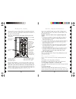
Buttons P1 thru P4 are used to store 4 position settings for each of
the 4 cameras controlled by buttons C1 thru C4.
1. Press C1.
2. Move the switch at the bottom from Normal to Program.
3. To store the first position for the camera controlled by C1. Press the
BLUE buttons to scan to the position you want. Press P1.
4. To store the second position for the camera controlled by C1. Press the
BLUE buttons to scan to the position you want. Press P2.
5. To store the third position for the camera controlled by C1. Press the
BLUE buttons to scan to the position you want. Press P3.
6. To store the fourth position for the camera controlled by C1. Press the
BLUE buttons to scan to the position you want. Press P4.
7. Move the switch back to Normal.
Press C2 and repeat steps 2 to 7 above to store 4 positions for Camera C2.
Press C3 and repeat steps 2 to 7 above to store 4 positions for Camera C3.
Press C4 and repeat steps 2 to 7 above to store 4 positions for Camera C4.
To clear all stored positions:
Move the switch at the bottom to Program. Press
Center
then move the
switch back to Normal.
W
ITH
THE
SWITCH
SET
TO
N
ORMAL
:
Press C1, then P1, P2, P3 or P4 to move to camera 1's 4 stored positions.
Press C2, then P1, P2, P3 or P4 to move to camera 2's 4 stored positions.
Press C3, then P1, P2, P3 or P4 to move to camera 3's 4 stored positions.
Press C4, then P1, P2, P3 or P4 to move to camera 4's 4 stored positions.
Press C1 then
Center
to center the position for camera 1.
Press C2 then
Center
to center the position for camera 2.
Press C3 then
Center
to center the position for camera 3.
Press C4 then
Center
to center the position for camera 4.
1. To control up to 4 Cameras, plug each one into its own Addressable
Power Supply, and set each power supply to the same Housecode you
set on the Transceiver and the Remote. Set each power supply to a
unique number between 1 and 4. Pressing any Camera button (C1, C2,
C3, or C4) turns on that camera (1, 2, 3, or 4) and turns the others (in the
group) off. Then, each press of either the
or
button turns on the
next or previous camera in the group of 4 while turning the current
camera off. You must set all cameras to the same channel as the Video
Receiver VR31A, or VR36A (Channel A, B, C, D).
2. To “Pan” or “Tilt” a camera: Press C1, C2, C3, or C4 to turn on the
camera. Then press a left or right BLUE button at the top to “Pan” the
camera left or right. Press a BLUE up or down button to “Tilt” the
camera up or down.
M
ULTI
-C
AMERA
S
YSTEMS
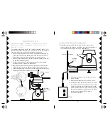
STOP! If you only own one Pan 'n Tilt Camera, you don't need to
read any further.
Important:
For a Multi Camera system you will need to install a
Transceiver (Model RR501 OR TM751, each sold separately). Set its
Housecode to match the CR14A Remote, and XM14A power supplies
you've installed.
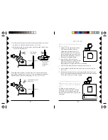
1. Set Housecode to
match the CR14A
Remote, and power
supplies.
2. Plug the Transceiver
into an AC outlet
located centrally in
your home.

