


I N S T A L L I N G T H E S Y S T E M
1-7
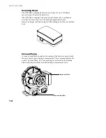
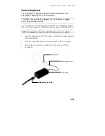
3. Make sure the Voltage Selection Switch—located below Line Cord
Receptacle—has been set to the proper line voltage for your region.
4. Connect one end of I/O Interface Cable to the Vacuum Pump I/O Port
on the Docking Station.
5. Connect other end of I/O Interface Cable to an I/O Port on the Vacuum
Pump Connect Box (either port can be used).
6. Connect the Line Cord to the Vacuum Pump AC Cord Receptacle.
7. Plug Line Cord into AC wall receptacle.
NOTE:
Vacuum Pump only operates during a measurement sequence.
Vacuum Pump I/O Port
Vacuum Pump
Connect Box
I/O Interface Cable
I/O Port
AC Cord Receptacle
Voltage Selection Switch
Line Cord
To AC Wall
Receptacle
Summary of Contents for ATD
Page 2: ......
Page 18: ...S E C T I O N O N E 1 10 ...
Page 33: ...B 1 A P P E N D I X B Parts List and Packaging Drawing ATD SHEET INSTRUMENT PARTS LIST ...
Page 34: ...A P P E N D I X B B 2 ATD SHEET PACKAGING DRAWING ...
Page 35: ...P A R T S L I S T A N D P A C K A G I N G D R A W I N G B 3 ATD NEWS INSTRUMENT PARTS LIST ...
Page 36: ...A P P E N D I X B B 4 ATD NEWS PACKAGING DRAWING ...
Page 37: ......


