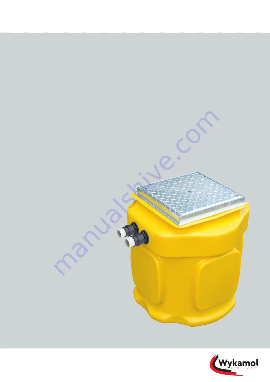
background image

WASTE WATER PUMPING SYSTEMS

Wykamol SumpFlo

Installation and operating guidelines

The Wykamol SumpFlo is a range of fully automatic waste water pump station, 
suitable for pumping ground water from a cavity membrane system and/or 
surface water from lightwells to a higher level.

Models

SumpFlo
SumpFloTwin (single discharge)
SumpFloTwin (twin discharge)
SumpFlo BBPS (single discharge)
SumpFlo BBPS (twin discharge)
SumpFloTwin BBPS (twin discharge)

Technical advice: 0845 400 6666
www.wykamol.com

Summary of Contents for SumpFlo

Page 1: ...er pump station suitable for pumping ground water from a cavity membrane system and or surface water from lightwells to a higher level Models SumpFlo SumpFloTwin single discharge SumpFloTwin twin discharge SumpFlo BBPS single discharge SumpFlo BBPS twin discharge SumpFloTwin BBPS twin discharge Technical advice 0845 400 6666 www wykamol com ...

Page 2: ... of SumpFlo BBPS twin pump configuration single discharge configuration 15 3 6 Installation of SumpFlo BBPS twin pump configuration twin discharge configuration 19 3 7 Installation of SumpFloTwin BBPS twin pump configuration twin discharge configuration 23 3 8 Electrical requirements 27 3 9 High level alarm 9V 27 3 10 AquaSafe Alarm 28 3 11 Battery backup pump system 28 3 11 1 Control panel operat...

Page 3: ...d which acts as a warning system to alert the end user if the water rises above the normal operating level within the chamber High Level Alarm kits can be purchased to installer specifications 1 PVC pipework configuration is available in single and twin discharge options upon request 2 3 SumpFlo BBPS battery backup system The system comprises of a polyethylene chamber stainless steel float bracket...

Page 4: ...r failure please refer to section 4 3 Battery Backup Pump System for details of battery life An Access Cover can be purchased to installer specifications 3 Site preparation and installation 3 1 Advisory It is important to note that these instructions are for guidance only and it is the installer s responsibility to satisfy themselves that the installation procedure is in accordance with the site c...

Page 5: ...ng that the float arm is not obstructed by for example the chamber wall inlets etc at its optimum reach Remove the nut located in the pump switch and push the float arm into place ensuring that the nut is securely replaced Prior to installing the internal pipe work please check the Non Return Valve is securely fixed to the pump outlet and ensure that the flap opens in the direction of the flow a U...

Page 6: ...you use 1 Class E PVC Pressure Pipe but should the installer wish to use 36mm OD Solvent Weld Waste Pipe white a PVC 1 Coupling Female TH TH 6 and a 32mm Male Iron 7 is supplied within the fittings kit To apply these connections apply PTFE tank to the male threads of the Tank Connector and Male Iron Screw the 1 Coupling Female TH TH 6 onto the Tank Connector following the same process for the Male...

Page 7: ...irit level across the chamber s opening The chamber MUST be ballasted with water at the same rate as backfilling such that the level difference between the water and the backfill does not exceed 150mm at any time Please ensure that when pouring the concrete backfill suitable steps are taken to prevent the concrete entering the chamber and any connected pipework 8 The system is supplied with an acc...

Page 8: ...e chamber Kit B requires secondary 240V 1 pump to be installed within the chamber No Qty Part description Qty supplied in Kit B Part code 1 2 PVC 1 Male Threaded Adaptor 1 8023 2 2 PVC 1 Elbow PL PL 90degree 1 8022 3 3 PVC 1 Socket Union PL PL 2 8027 4 2 PVC 1 Class E Pressure Pipe 0 5mtr 1 8024L 5 1 PVC 1 Tank Connector 0 8028 6 1 PVC 1 Coupling Female TH TH 0 8030 7 1 32mm Male Iron 0 9010 8 1 P...

Page 9: ... e Place the Socket Union position no 3 over the plain end of the Tank Connector do not use solvent glue at this stage f Measure and cut a length of horizontal Pipe required between the placed Socket Union 3 and Tee Piece 8 to be positioned above and between the Male Threaded Adaptors 1 taking into your measurement the length of pipe inserted into the fittings do not use solvent glue at this stage...

Page 10: ...ures and that they are not transferred onto the chamber 5 In all instances the chamber MUST be positioned on a flat level concrete base of dimensions sufficient to fully support the base of the chamber Once the reinforced waterproof concrete sump has been formed lay a 100mm mass concrete within your reinforced waterproof concrete sump carefully position the chamber onto the WET concrete base ensur...

Page 11: ...should the vertical lift exceed 3 meters 11 It is extremely important that once the chamber has been installed before the pump is installed the system is flushed through and all sand silt rubble and general debris removed from the chamber FAILURE TO DO THIS WILL INVALIDATE THE WARRANTY ON THE PUMPS 12 Install the pumps and water level monitoring cables and draw these cables through the cable duct ...

Page 12: ... twin discharge configuration Kit C requires secondary 240V 1 pump to be installed within the chamber No Qty Part description Qty supplied in Kit C Part code 1 2 PVC 1 Male Threaded Adaptor 1 8023 2 2 PVC 1 Elbow PL PL 90degree 1 8022 3 2 PVC 1 Socket Union PL PL 1 8027 4 2 PVC 1 Class E Pressure Pipe 0 5mtr 1 8024L 5 2 PVC 1 Tank Connector 1 8028 6 2 PVC 1 Coupling Female TH TH 1 8030 7 2 32mm Ma...

Page 13: ...tage e Measure and cut a length of horizontal Pipe required between the placed Socket Union 3 and Elbow 2 to be positioned directly above the Male Threaded Adaptor 1 taking into your measurement the length of pipe inserted into the fittings do not use solvent glue at this stage f Measure and cut a length of vertical Pipe required between the placed Elbow 2 and Male Threaded Adaptor 1 taking into y...

Page 14: ...d discharge to the chamber 7 Whilst the concrete base is still WET backfill the chamber with a mass concrete The concrete must be evenly poured around the chamber ensuring that no voids are left within the concrete Care must be taken to ensure that any pipes or other connections made are not damaged During the concrete pour ensure that the chamber is vertical by use of a spirit level across the ch...

Page 15: ...BBPS system to be installed within the chamber No Qty Part description Qty supplied in Kit D Part code 1 1 PVC 1 Male Threaded Adaptor 0 8023 2 3 PVC 1 Elbow PL PL 90degree 2 8022 3 3 PVC 1 Socket Union PL PL 2 8027 4 2 PVC 1 Class E Pressure Pipe 0 5mtr 1 8024L 5 1 PVC 1 Tank Connector 0 8028 6 1 PVC 1 Coupling Female TH TH 0 8030 7 1 32mm Male Iron 0 9010 8 1 PVC 1 Tee Piece 1 8032 9 3 PVC 1 PL ...

Page 16: ...PL TH Barrel Nipples 9 Screw 1no PL TH Barrel Nipple 9 directly into the bilge pump horizontal outlet connection do not overtighten Place 1no Elbow 2 onto the PL TH Barrel Nipple located into the bilge pump transferring flow direction from horizontal to vertical Screw 2no PL Th Barrel Nipples 9 directly into the 1 Brass Non Return Valve V supplied from the BBPS kit Place the Brass Non Return Valve...

Page 17: ...ion for the pumping station It is extremely important to site the system with permanent access in mind for routine maintenance of the system 3 Prepare the chamber for all connection incoming pipe s inlet s and cable duct To do this you must select the location and drill the appropriate sized inlet s and cable duct for the connections see Section 7 Accessories for inlet and cable duct rubber seals ...

Page 18: ...tering the chamber and any connected pipework 8 The system is supplied with an access cover this is loose and should sit directly above the top of the chamber access shaft Please note that the chamber is only suitable for installation to a maximum of 300mm deeper than supplied from finished floor level 9 Please note that the ballast water inside the chamber should not be removed until the backfill...

Page 19: ...it E requires full BBPS system to be installed within the chamber No Qty Part description Qty supplied in Kit E Part code 1 1 PVC 1 Male Threaded Adaptor 0 8023 2 3 PVC 1 Elbow PL PL 90degree 2 8022 3 3 PVC 1 Socket Union PL PL 2 8027 4 2 PVC 1 Class E Pressure Pipe 0 5mtr 1 8024L 5 2 PVC 1 Tank Connector 1 8028 6 2 PVC 1 Coupling Female TH TH 1 8030 7 2 32mm Male Iron 1 9010 8 3 PVC 1 PL TH Barre...

Page 20: ...eaded Adaptor is in direct line with the installed Tank Connector Check that the Pump Float Arm is free from any obstruction at its optimum reach e Place the Socket Union position no 3 over the plain end of the Tank Connector relating to the Primary Pump pipework do not use solvent glue at this stage f Measure and cut a length of horizontal Pipe required between the placed Socket Union 3 and Elbow...

Page 21: ...uld be as per point g and h as above 2 Select a suitable location for the pumping station It is extremely important to site the system with permanent access in mind for routine maintenance of the system 3 Prepare the chamber for all connection incoming pipe s inlet s and cable duct To do this you must select the location and drill the appropriate sized inlet s and cable duct for the connections se...

Page 22: ...tering the chamber and any connected pipework 8 The system is supplied with an access cover this is loose and should sit directly above the top of the chamber access shaft Please note that the chamber is only suitable for installation to a maximum of 300mm deeper than supplied from finished floor level 9 Please note that the ballast water inside the chamber should not be removed until the backfill...

Page 23: ...nstalled within the chamber No Qty Part description Qty supplied in Kit F Part code 1 2 PVC 1 Male Threaded Adaptor 1 8023 2 3 PVC 1 Elbow PL PL 90degree 2 8022 3 4 PVC 1 Socket Union PL PL 3 8027 4 4 PVC 1 Class E Pressure Pipe 0 5mtr 3 8024L 5 2 PVC 1 Tank Connector 1 8028 6 2 PVC 1 Coupling Female TH TH 1 8030 7 2 32mm Male Iron 1 9010 8 1 PVC 1 Tee Piece 1 8032 9 3 PVC 1 PL TH Barrel Nipple 3 ...

Page 24: ...alled Tank Connector Check that the Pump Float Arm is free from any obstruction at its optimum reach e Place the Socket Union position no 3 over the plain end of the Tank Connector relating to the Primary Pump pipework do not use solvent glue at this stage f Measure and cut a length of horizontal Pipe required between the placed Socket Union 3 and Elbow 2 to be positioned directly above the Male T...

Page 25: ...or the Bilge Pump taking into your measurement the length of pipe inserted into the fittings do not use solvent glue at this stage p Chamfer clean and dry the connection edges of the PVC lengths using an appropriate PVC Solvent Cleaning Fluid making sure these areas on the pipe and within the fitting are free from any debris dirt q Check all the pipework is in place correctly before applying plent...

Page 26: ...d discharge to the chamber 7 Whilst the concrete base is still WET backfill the chamber with a mass concrete The concrete must be evenly poured around the chamber ensuring that no voids are left within the concrete Care must be taken to ensure that any pipes or other connections made are not damaged During the concrete pour ensure that the chamber is vertical by use of a spirit level across the ch...

Page 27: ...le slack on the cable to allow for the pump s to be removed for maintenance All unswitched fused spurs should be sited adjacent to the pumps control panels The unswitched fused spurs for the pumps should be minimum of 1 metre above the top of the pump station chamber 5 Please refer to Electrical Configuration see section 8 6 This work should be entrusted to a qualified electrician in accordance wi...

Page 28: ...on arm is down and fixed into position using the plastic washer and nut The float switches should be located within the chamber ensuring that the following configuration is adhered to Float Position Run Float Top of bracket High Level Alarm Float Middle of bracket float is to be higher than the primary pump float switch Off Float Bottom of bracket 4 The electrical float cables should be drawn thro...

Page 29: ... has tripped blockage mains power is not present or a battery fault Please speak with your supplier or call Edincare Pumps on 01442 211554 Green Indicator Running This indicates that the backup pump is in operation Large Red Indicator c w Sounder High Level Alarm This indicates that the water level within the pumping station is at an excessive level A fault maybe present with the pumping station A...

Page 30: ...2800rpm per pump Max Vertical Output 6 7m 12 5m Max Horizontal Output 50m 50m Max Flow Rate 2 9 l s 3 9 l s Max Liquid Temp 50 C 50 C Discharge size 1 32mm 1 32mm Free passage 10mm 10mm Cable Length 5m 5m Colour Yellow Yellow 4 2 Weight excluding packaging Model Weight EA31 Pump Weight EA33 Pump SumpFlo 14kg 16kg SumpFloTwin single discharge 20kg 23kg SumpFloTwin twin discharge 20kg 23kg SumpFlo B...

Page 31: ...Alarm The system conforms to The Low Voltage Directive EN61010 2010 The EMC Directive EN55014 2006 A1 and EN55014 2 2015 Model AquaSafe Alarm Power Supply 230V AC 50hZ Rated Power 10VA Internal Battery 6V 1 3AH Sound Alarm Level 85dB Main Power Cable Length 1m Weight 0 5kg Material ABS Colour Grey Operating Temperature 10 C to 40 C 4 5 Battery backup pump system Model BBPS Power supply to panel 23...

Page 32: ...battery backup pump 0 0 0 1 1 1 Brass non return valve 0 0 0 1 1 1 24V battery backup pump control panel 0 0 0 1 1 1 Mini float switch 0 0 0 3 3 3 1 1 4 PVC pipework kit Kit A Kit A Kit B Kit A Kit C Kit A Kit D Kit A Kit E Kit A Kit F 7 Accessories Product name Weight Product code AquaSafe Alarm Mini 22070W 1 brass gate valve 10003 110mm rubber seal drainage inlet 17010 50mm rubber seal inlet cab...

Page 33: ... SumpFlo 33 44 Installation and operating guidelines Technical advice 0845 400 6666 www wykamol com 8 Electrical configuration 8 1 SumpFlo 240V pump High level alarm 9V battery Unswitched fused spur Suction cup sensor Distribution board ...

Page 34: ...amol SumpFlo 34 44 Installation and operating guidelines Technical advice 0845 400 6666 www wykamol com 240V pump 240V pump High level alarm 9V battery Unswitched fused spurs Suction cup sensor Distribution board 2 1 8 2 SumpFloTwin ...

Page 35: ...pFlo 35 44 Installation and operating guidelines Technical advice 0845 400 6666 www wykamol com Stop float High level float Start float Float bracket 240V pump Unswitched fused spurs Distribution board Control panel 24V pump 8 3 SumpFlo BBPS ...

Page 36: ...4 Installation and operating guidelines Technical advice 0845 400 6666 www wykamol com 24V pump Stop float High level float Start float Float bracket 240V pump 240V pump Unswitched fused spurs Distribution board Control panel 1 2 8 4 SumpFloTwin BBPS ...

Page 37: ...lines Technical advice 0845 400 6666 www wykamol com 9 Wiring diagrams Wiring Diagrams can be found within the panel control s Should you require further assistance please contact our technical helpdesk on 01442 211554 from 08 30 17 30 Monday to Friday 9 1 Battery backup pump system ...

Page 38: ... 24hours from time of delivery Please refer to the parts list in Section 6 11 Maintenance All maintenance works inspections and services MUST be undertaken by a technically qualified competent company engineer When undertaking works within the chamber suitable measures MUST to taken to ensure safe access in accordance with current safety regulations see section 12 Please refer to section 14 for fu...

Page 39: ...ain or alter the electrical installation of that dwelling from fire and injury including electric shock this should be done in accordance with the latest IET wiring regulations BS7671 The following works should only be done by qualified and authorized electricians Safeguard Europe disclaims all responsibility for work done by untrained or and unauthorized personnel Heed operating voltage as shown ...

Page 40: ...arth conductor should be the last conductor to come loose from the first terminal This applies to both ends of the cable Ensure the correct earthing of the pump and control system DO NOT OPEN THIS UNIT IF NOT QUALIFIED TO DO SO To reduce the risk of electric shock do not remove cover No user serviceable parts inside Refer servicing to qualified service personnel DISCONNECT FROM MAINS BEFORE REMOVI...

Page 41: ...it your schedule Reduced emergency call out rates Provide full reporting on all works undertaken this includes current condition of equipment and any recommended works Preferential scheduling of emergency call outs Increased life expectancy of equipment Reduced risk of breakdowns with their associated costs and inconvenience Free technical advice available via our help line Fully trained service e...

Page 42: ...WASTE WATER PUMPING SYSTEMS Wykamol SumpFlo 42 44 Installation and operating guidelines Technical advice 0845 400 6666 www wykamol com ...

Page 43: ...WASTE WATER PUMPING SYSTEMS Wykamol SumpFlo 43 44 Installation and operating guidelines Technical advice 0845 400 6666 www wykamol com ...

Page 44: ... wykamol com 44 0 845 400 6666 wykamol group wykamolgroup wykamolgroupltd Our policy is one of continuous product improvement we reserve the right to change specifications and prices without prior notice All information is given in good faith No responsibility can be accepted for errors omissions or incorrect assumptions ...

Reviews: