Page | 32
•
Then it will check the EEPROM, if there is a fault “EP” will be
displayed. This would indicate there is a
fault with the Fridge Main Controller Board, replace the Fridge Main Controller Board. See
Appendix
K: Fridge Controller Board Replacement Procedure
for directions.
•
Last check is for a 3-
minute delay, “BR” would be
displayed. This would indicate there is a fault with
the Fridge Main Controller Board, replace the Fridge Main Controller Board. See
Appendix K: Fridge
Controller Board Replacement Procedure
for directions.
iii.
At this point you will see all of the individual LED sections of the UI lighting up in sequence (sort of racing
across the 7 segment LED display)
iv.
Press the “ ” icon to display current temp.
v.
Press the “+” icon to turn on the Compressor and fans (note that when the board is sending a signal to
the compressor, there is a dot on the 7 segment LED that illuminates, almost like a decimal dot after the
2nd character. This is also true for regular operation, not just test mode). Pressing the “
-
“ icon you can
turn them off.
vi.
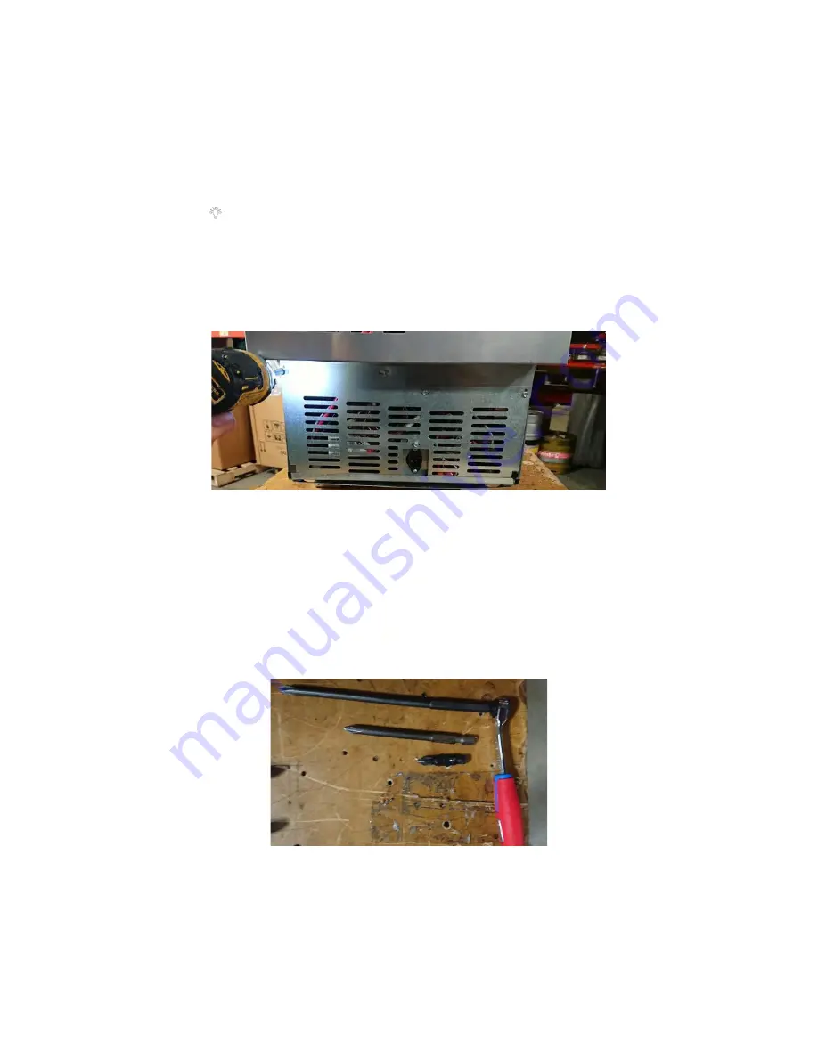
Remove 5 lower back panel screws.
See Figure 67.
vii.
Place hand on compressor to feel if it is running (may or may not be warm to the touch). If compressor is
not running, the inverter is the likely failure point so replace it. If the compressor is functioning, the
inverter is not at fault.
viii.
Remove Inverter Cover:
•
Use a small ratcheting driver with a Philips bit similar to below: (note all can be done with small
configuration or with regular screwdriver if needed, just a bit easier with a couple length options).
See Figure 68.
•
Remove one screw with short (A) Philips bit.
See Figure 69.
Figure 67: Rear Cover Installed.
Figure 68: Suggested tools shown.
Summary of Contents for JoeTap NITCOM
Page 55: ...Page 55 Appendix C JoeTap NITCOM 110V Wiring Diagram ...
Page 56: ...Page 56 Appendix D John Guest Speed Fit Guide ...
Page 79: ...Page 79 Appendix J Fridge Functionality Maintenance and Troubleshooting Guide ...
Page 80: ...Page 80 ...


