


Installation
Cleaning Air Box
3 - 2
ba75731e02
02/2008
Connecting the
compressed air hose
and intake filter
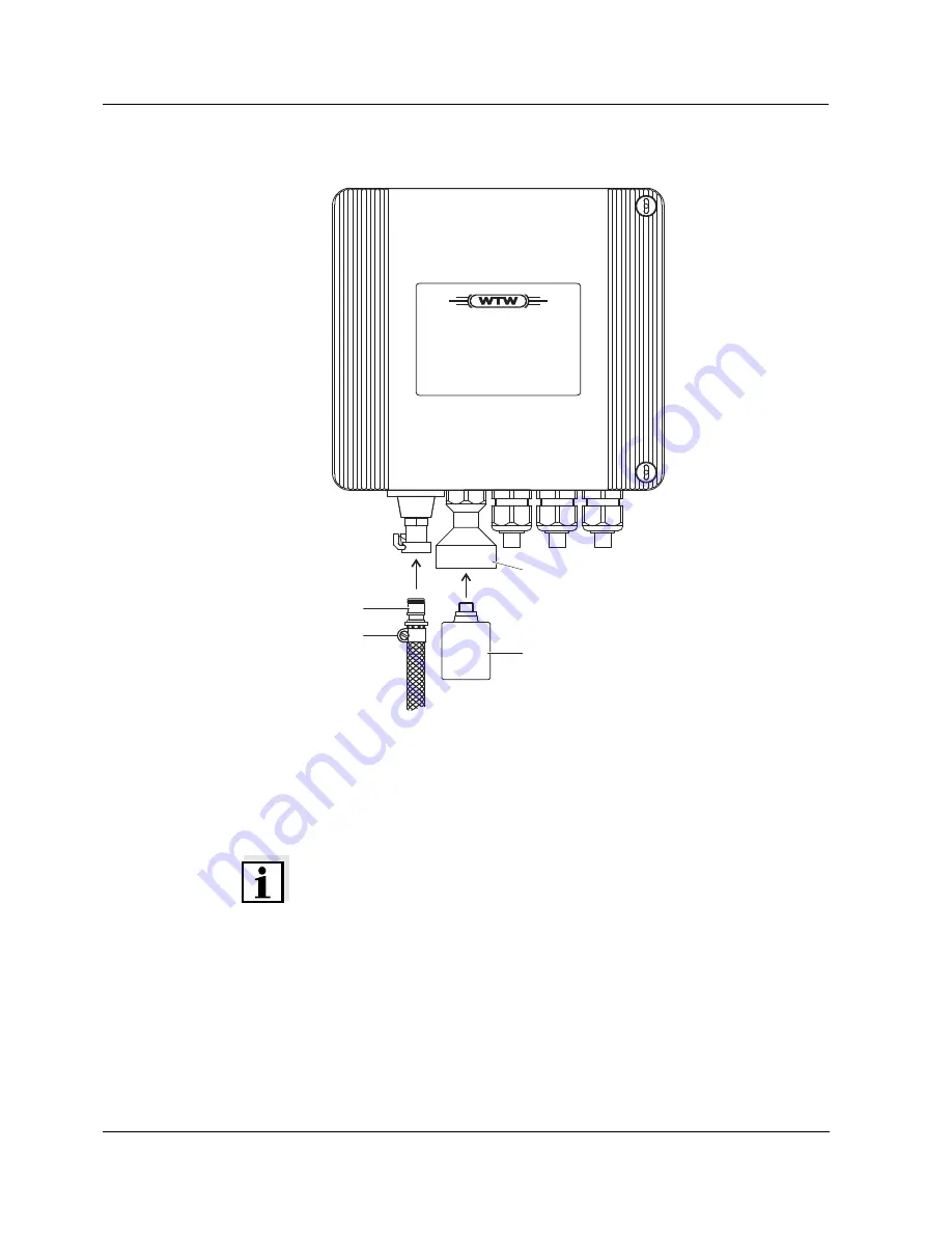
Fig. 3-1
Connecting the
compressed air hose and intake air filter
To connect the compressed air hose use the supplied fitting (pos. 1 in
Fig. 3-1) and secure the compressed air hose with the supplied hose
clip (pos. 2). Screw the intake air filter (pos. 3) into the filter socket (pos.
4) by hand.
Note
The cleaning nozzles at the sensor may only be immersed 1.5 m max.
When installing the compressed air hose make sure no water that
possibly remains in the hose can enter the Cleaning Air Box.
Cleaning Air Box
1
2
4
3


