


2.1.2.
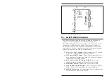
Control Module Back Panel
À
Remote Switch Connector:
For connection to an optional
external remote. For interface description, see Appendix A.
Á
Switch Module Labels:
Three Labels which denote “A”,
“Common”, and “B” connectors on each Switch Module.
Â
SetUp Switches:
A bank of ten DIP switches used to select
baud rate, parity, duplex mode, and other parameters.
Ã
Input Connector:
For connection to previous bank when
daisy chaining multiple RAB-14A units.
Ä
Output Connector:
For connection to next bank when daisy
chaining multiple RAB-14A units.
Å
Command Port:
For optional connection to a PC. Allows
control by ASCII commands.
Æ
Fuse
Ç
Power Switch
È
AC Power Cable
É
Frame Connector & Ribbon Cable
2-2
RAB-14A User’s Guide
Figure 2.2: Control Module Back Panel


