


3.
Installation
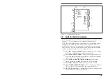
3.1.
Control Module DIP Switches
The DIP Switches on the Control Module back panel are used to
select the Baud Rate, Parity, Duplex and other parameters.
Several parameters selected by the DIP Switches will only apply
when multiple RAB-14A units are daisy chained together. These
parameters include the designation of Master and Satellite Banks
(additional RAB-14A rack units) and the Bank Number. For more
information on connecting multiple units, please refer to
Section 3.5.
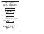
3.1.1.
Bank Number (Sw1 - Sw4)
SetUp Switches one through four assign an address or “Bank
Number” to each RAB-14A unit. If the RAB-14A will be operated
as a stand-alone unit with fourteen channels or less, the Bank
Number should be “01". If several units will be daisy chained to
provide more than fourteen channels, please refer to Section 3.5
and set Bank Numbers accordingly.
Bank Number
Sw1
Sw2
Sw3
Sw4
Not Defined
0
0
0
0
01
1
0
0
0
02
0
1
0
0
03
1
1
0
0
04
0
0
1
0
05
1
0
1
0
06
0
1
1
0
07
1
1
1
0
08
0
0
0
1
09
1
0
0
1
10
0
1
0
1
11
1
1
0
1
12
0
0
1
1
13
1
0
1
1
14
0
1
1
1
3-1


