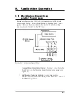
3.
Configure Monitor Mode:
Access the PLS command
mode as described in Section 5.2. At the PLS> command
prompt, type
/M
[Enter]
to display the Monitor Mode
Parameters Menu. Note that the Monitor Mode Parameters
Menu is not available in User Mode. Set Monitor Mode
Parameters as follows:
a)
Item 1 - Monitor Mode:
On.
Note:
Do not enable the Monitor Mode until you
have finished defining the other Monitor Mode
parameters.
b)
Item 2 - Switch if Level:
0 - Low.
c)
Item 3 - Switch to Position:
B.
d)
Item 4 - Delay Period:
1 Minute.
e)
Item 5 - Return:
Off (Note that if you wanted the
A/B circuits to return to their original positions if the
monitored line goes high again, then this item would
be enabled.)
f)
Item 6 - Circuits to Switch:
Enable the Monitor
Mode at circuits 2 and 3.
4.
Set Circuit Parameters:
From the PLS command prompt,
type /P 2 [Enter] to display the Circuit 2 Parameters
Menu. Use item 4 (Default Position) in the Circuit
Parameters Menu to set the default state for Circuit 2 to
"A". Repeat this procedure for Circuit 3 (use the /P 3
command to access the Circuit 3 Parameters Menu.)
5.
Operation:
When the DTR signal is present (high),
Circuits 2 and 3 will remain in the default (A) position. If
the DTR drops for more than one minute, PLS A/B
Circuits 2 and 3 will be switched to the "B" position.
9-2
PLS-345 - Physical Layer Switch; User's Guide
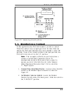
Figure 9.2: AUX Port Connection
Summary of Contents for PLS-345
Page 1: ...WTI Part No 13236 Rev A PLS 345 Physical Layer Switch User s Guide...
Page 2: ......
Page 12: ...2 4 PLS 345 Physical Layer Switch User s Guide...
Page 38: ...6 4 PLS 345 Physical Layer Switch User s Guide...
Page 61: ......


