3
K
K
Installation
If there is a consultant’s specification covering the work for the project then this takes precedence over the
method of installing grease traps detailed in these instructions which is for guidance only.
The grease trap should be located as close as possible to the building being served. Alternatively it can be sited
within the building when fitted with an airtight seal.
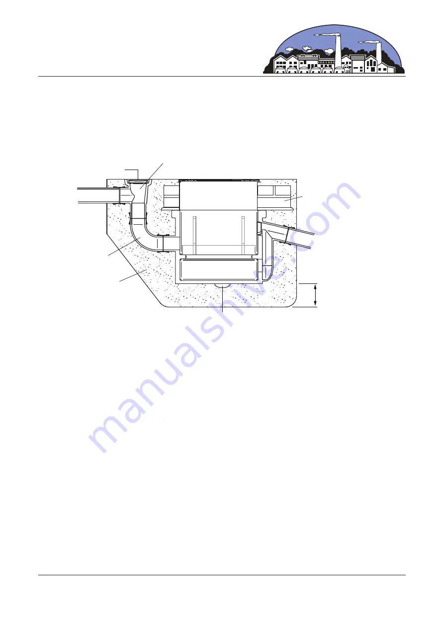
Square Hopper
with back inlet
Grate
Cover and Frame
90˚ Bend
Engineering brick work
and mortar surround
Relief for sling
150mm
Concrete bed
and surround
Outlet
Inlet
Hole Preparation
Excavate a hole of sufficient size and depth taking into consideration:-
• The size of the grease trap.
• Allow for 150mm of concrete below the trap and around all 4 sides.
• From the pathway surface the minimum depth required for the square hopper and 90˚ bend. Greater depth
can be accommodated using a length of pipe between the hopper and bend but ease of removal of the tray
must be considered.
• The depth of the outlet pipe to the main drain pipework.
Excavate the trenches for the inlet pipe from the catering establishment and the outlet pipe to the main drain
pipework.
Foundations
Lay a bed 150mm deep of - 8500 GEN 3 concrete (20N/mm³ and 20mm slump) with little moisture.
Form a relief in the position where the sling to lower the trap into position will be located to allow the sling to
be removed.
Lifting
The clay grease traps must be lifted using mechanical means.
Use a loop sling around the trap body positioned to balance the body when lifted.
Appropriate mechanical lifting devices must be used.
Avoid manual handling except when final positioning.
Check the correct orientation of the body, the ‘Inlet’ is clearly marked above the inlet connection.
Once the trap has been lowered and positioned remove the sling by pulling through the relief in the bed.


