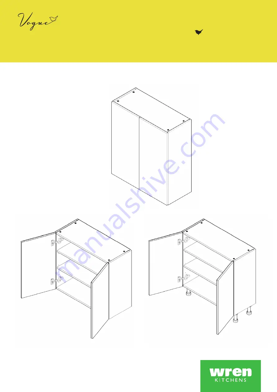
WALL / SHALLOW BASE UNIT
700 - 800 Assembly Guide
For Internal Use: FI.WR.INS.035_WKIN00125_MULTI_700-800_WALL_ShallowBASE_Rev8.indd
800 WALL
800 BASESHALLOW
700 WALL
Page 1: ...WALL SHALLOW BASE UNIT 700 800 Assembly Guide For Internal Use FI WR INS 035_WKIN00125_MULTI_700 800_WALL_ShallowBASE_Rev8 indd 800 WALL 800 BASE SHALLOW 700 WALL...
Page 2: ...mm Screw M x4 Cover Cap N x2 Door Buffer Z x10 Shelf Peg Plastic T x12 Back Panel Support Clip Hanging Bracket Plate X2 Screws Not Included Hinge Mounting Plate X4 Inc Screws Hinge X4 Inc Screws Corne...
Page 3: ...am Locks H this will expand the Cam Dowels G and tighten the unit together NB All cam locks H are to be positioned facing the outside of the unit carcase for ease of tightening Do not use power tools...
Page 4: ...nsert cam lock H Hand tighten all cam locks H this will expand the cam dowels G and tighten the unit together NB All cam locks H are to be positioned facing the outside of the unit carcase for ease of...
Page 5: ...and positioned to allow the hanging brackets and corner gussets to be fitted Once in place tighten screws Step 10 Ensure unit is square B A C B A T B From Base From Top 126mm 126mm 94mm 94mm L L Step...
Page 6: ...ew through Back Panel Pilot hole M Detail B L L L L Detail B Step 15 Drill a small pilot hole through the centre of the corner gussets through the back of the unit Use this hole at the end of the proc...
Page 7: ...Rotate the screw clockwise to move the unit up Anti clockwise for down Step b Adjust the depth using centre screw Step c Screw the red screw until it touches the plate to lock in position Hanging Bra...
Page 8: ...aps M provided Screws for fixing to walls are not provided as these vary depending on your wall material and construction Ensure appropriate fixings for wall constructions are used Step 20 Secure corn...
Page 9: ...HALLOW BASE UNITS ONLY Ensure legs are rotated as shown so that part of it is supporting the end panels B Step 23 Secure each of the legs into place with 4 x 15mm screws L per leg L L L L B B C C Step...
Page 10: ...ure Hinge Cover Caps Step 29 Fit cover caps to hinge Adjust Soft close to suit Step 28 Adjust hinge to suit As shown below Hinge Plates The top and bottom hinges MUST be adjusted to the SAME STRENGTH...
Page 11: ...Page 10 For Internal Use FI WR INS 035_WKIN00125_MULTI_700 800_WALL_ShallowBASE_Rev8 indd...
Page 12: ......