background image

11

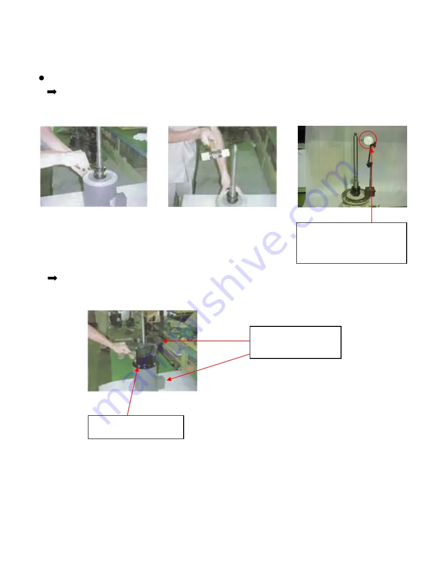
Motor Assembly:Installation of  the joint shaft to the motor

ORDER OF ASSEMBLY

(continued)

1. Install the joint shaft to the 
motor.

2. Adjust the shaft run out by a 
hummer.

3. Check the shaft run out by the 
dial gauge.

The shaft run out should be 
within 50 micrometer.  Repeat 
step 1 to 3 until the shaft run 
out is within 50 micrometer.

As the pictures shown below, install the joint shaft to the motor and check the shaft run out the dial gauge.

Assemble the motor bracket to the motor by bolts.  When you install the bracket to the motor, please be 
careful about the direction of the bracket and the motor.  The terminal box of the motor and the nameplate 
should be the same direction.

The terminal box and 
the nameplate should be 
the same direction.

Fasten the motor and the 
motor bracket with bolts.

Summary of Contents for YD-25NSF

Page 1: ...YD 25NSF YD 40NSF YD 50NSF Version WCA 0202 INSTRUCTION MANUAL SELFREE SEALLESS VALVELESS SELF PRIMING PUMP NON METALLIC CARBON FIBER REINFORCED POLYPROPYLENE...

Page 2: ...or bearing This manual will explain how operate and maintain your pump properly Please read it to effectively use your pump for an extended period HANDLING UPON RECEIPT PREFACE FEATURES 21 THE PRINCI...

Page 3: ...ion Non compliance can lead to some injury and or property damage This symbol indicates a warning or precaution This symbol indicates a required action This symbol indicates a prohibited action Do not...

Page 4: ...the pump in accordance to its specifications Do not damage modify or stretch the power cord Heating or placing heavy objects on the cord will damage it causing fire and or electric shock Do not modif...

Page 5: ...quality resin construction CFR PP CFR PVDF The entire pump and its component parts are flawless molded with an all resin construction The pump s stability and quality are assured even in the harshest...

Page 6: ...priming chamber guided by the impeller after the pump is turned on In the self priming chamber the air and water separate as they rotate The water is propelled into the impeller as it leaves the self...

Page 7: ...3 EXAMPLES OF USE Pumping transport from a drainage tank or a chemical tank 2 Transferring circulating high temperature plating liquid to a filtering tank 1 WARNING THIS USE NOT APPLICABLE...

Page 8: ...4 SPECIFICATION AND PERFORMANCE CURVES...

Page 9: ...5 DIMENSIONAL AND PARTS DRAWING Note Marked dimension varies depending on the motor size...

Page 10: ...Impeller with Sleeve O ring Casing Assembly Pump Base Motor Oil Seal Motor Bracket Impeller Locking Sleeves Overflow Pipe O ring Pump Body O ring Casing Assembly Drain Plug Packing Pump Body Seal Case...

Page 11: ...3 CFRPP Casing 12 FPM Packing for drain priming plug 11 CFRPP Drain plug 10 CFRPP Impeller with sleeve 9 PPS Impeller locking sleeves 8 FPM O ring 7 CFRPP Cleaning plug 6 CFRPP Pump body 5 CFRPP Primi...

Page 12: ...mp and casing to be distorted and or damaged by heat To prevent the self priming capacity from lowering it is necessary to have a vertical pipe longer than 3 3 ft 1 m attached to the outlet with a byp...

Page 13: ...at room temperature Check Valve Approx 3 3 ft 1 m d A 11 5 ft 3 5 m YD 50NSF 9 8 ft 3 0 m YD 40NSF 8 2 ft 2 5 m YD 25NSF A 3 The limit of the suction height self priming capacity assumes that the suct...

Page 14: ...e o rings to the pump flange Installation of the flange to the pump body Installation of the discharge elbow to the pump body Installation of the motor assembly to the pump body Installation of the im...

Page 15: ...aft run out is within 50 micrometer As the pictures shown below install the joint shaft to the motor and check the shaft run out the dial gauge Assemble the motor bracket to the motor by bolts When yo...

Page 16: ...ber portion must be turned Pump Body Assembly Installation of the o rings to the pump flange Place the following four o rings onto each specified place on the pump upper flange O ring for the priming...

Page 17: ...he direction of each part Pump body Pump Body Assembly Installation of the discharge elbow to the pump body The pump body is put on the pump upper flange with o rings Weight the pump body for a certai...

Page 18: ...l adjustment Bolt with washer and nut with spring washer and washer Bolt size M10x65 Nut sieze M10 Pump Body Assembly Installation of the impeller to the pump body Put the dry seal to the impeller up...

Page 19: ...7 21 mm 3 Measure a distance of Z from the top of the casing to the bottom of the casing Z measures as 0 858 21 8 mm 4 The GAP calculation between the impeller and the casing GAP Z Y 0 032 0 8 mm MUST...

Page 20: ...Place an o ring onto the o ring groove on the casing Pump Body Assembly Installation of the pump casing to the pump body 1 Place the casing with o rings onto the pump body and fasten them with slotte...

Page 21: ...to the pump casing 3 Install the priming plug with a packing to the pump 1 Place the pump base on the pump and fasten them with hex bolts and nuts ORDER OF DISASSEMBLY Disassemble the pump in the rev...

Page 22: ...sure switch Improper insulation Burn out of the motor Damage to the motor bearing Rotate only the motor manually If it is heavy it is out of order Rotate only the pump manually Unable to start 1 Defec...

Page 23: ...n the suction pipe 1 Liquid is easily to foam 2 Liquid temperature and its specific gravity are over its maximum permissible limit 3 Strainer foot valve and impeller are clogged with foreign particles...

Page 24: ...tion Check the vibration or noise source Inside the pump Motor Bearing Piping and valve section Foundation section Low suction pressure due to excess suction lift Cavitation Foreign particles in sucti...

Page 25: ...omer and the manufacturer Travel expenses for non warranted repair service to a remote location will be the responsibility of the customer 6 Damages and costs of damages incurred as a result of pump f...

Page 26: ...When ordering replacement or spare parts please provide the part names part numbers and material listed in the table on page 7 When requesting repair service please provide us with the following infor...

Page 27: ...E mail wcusa worldchemicalusa com Website http www worldchemicalusa com North South America Tousen Higashi Azabu Bldg 7th Floor 1 5 2 Higashi Azabu Minato ku Tokyo 106 0044 Japan TEL 03 3588 1140 FAX...

Reviews: