background image

Check the drill and package contents

16

Check the drill and package contents

Parts of the drill are greased to provide protection against corrosion. 

•  Wear suitable work clothing. Place all parts on a piece of cardboard 

or similar.

1. Lift the drill out of the packaging using both hands.

2. Place the drill on a level, stable base, e.g. on a workbench. 
3. Check whether the drill or the individual parts exhibit any damage. If this is the 

case, do not use the drill. Contact the manufacturer at the service address specified 

on the warranty card.

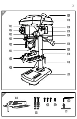
4. Check to make sure that all parts are included (see 

Fig. A

,

B

and 

L

).

Assembly

•  You will need an AF 13 open-ended spanner to mount the drill 

column 

7

•  Make sure that the drill is completely and properly assembled 

before you start it.

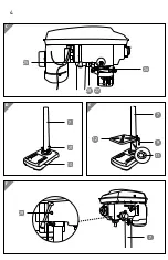
1. Place the base plate 

10  

on a solid and stable base such as a workbench. Use the 

three hexagon screws 

21

 to tightly screw the drill column to the base plate  

(see 

Fig. D

).

.

2. Slide the drilling table 

12

 onto the drill column and fix it in place with the rotary 

knob for setting the height 

9

 (see 

fig. E

).

.

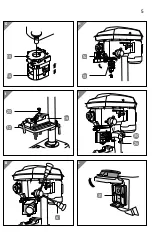
3. Place the entire machine head on the drill column (see 

fig. F

). 

Screw the two grub screws 

29

 tight to secure the machine head. 

4. Insert the foldable chip guard 

15  

with the screw mounted protective hood 

14  

on the spindle and screw it in place (see 

fig. G

). 

5. With a jerk and applying some force, fold the protective hood upwards and 

place the chuck 

13

 onto the spindle (see 

Fig. H

). The chuck must audibly and 

noticeably lock into place. Use a rubber mallet for this. 

6. Fix the line laser 

26

 using the screw for the line laser 

22

 onto the machine head 

(see 

Fig. J

).

Summary of Contents for WZ-TB 13 L

Page 1: ...BENCH DRILL WZ TB 13 L User Manual Original instructions ID 05007 m y hansecontrol c o m M A N U A L DEVELOPED IN G E R M A N Y User friendly Manual...

Page 2: ...the drill and package contents 16 Assembly 16 First use 17 Operation 17 Preparations 18 Emergency stop switch 18 Setting the speed 19 Speed table 21 Setting the height of the protective hood 22 Clampi...

Page 3: ...3 A B 1 3 4 5 6 7 8 9 10 11 12 13 14 15 16 17 2 19 20 21 22 23 18 24...

Page 4: ...4 F 29 7 21 10 12 7 9 D E C 27 28 7 11 26 25...

Page 5: ...5 14 13 15 14 19 12 20 I L G H K J 6 30 26 31...

Page 6: ...oldable chip guard 16 Arrow mark for setting the drill depth 17 Emergency stop switch 18 Clamping screw for setting the drilling depth 2 19 Vice 20 Fixing screw 2 washer 4 spring washer 2 nut 2 21 Hex...

Page 7: ...Keep this user manual in a safe place for future reference If you pass the drill on to third parties please be absolutely sure to include this user manual Explanation of symbols The following symbols...

Page 8: ...ols with a shank diameter from 1 5 up to a maximum of 13 millimetres and cylindrical tool shank Tools with a taper shank MK2 can also be used The drill must not be operated continuously for more than...

Page 9: ...h attributed to hand and arm vibration if the drill is used over a prolonged period of time is not guided in a controlled manner and maintained properly risk of injury if long hair loose fitting cloth...

Page 10: ...it up or for pulling or unplugging it from the socket Keep cord away from heat oil sharp edges and moving parts Damaged or entangled cords increase the risk of electric shock e When operating a power...

Page 11: ...here is an option for installing dust suction devices and dust containers these should be attached and used correctly Use of dust collection can reduce dust related hazards h Do not be lulled into a f...

Page 12: ...nditions and the work to be performed Use of the power tool for operations different from those intended could result in a hazardous situation h Keep handles and handle surfaces dry clean and free fro...

Page 13: ...pecified on the power tool Accessories that rotate faster than permissible may break and be projected Safety notes for the line laser Do not point the laser beam at persons animals or reflective surfa...

Page 14: ...ssary clean the contacts of the batteries and device before inserting them e g with a piece of emery cloth Make sure that the polarity is correct when inserting the batteries Do not use old and new ba...

Page 15: ...power cable so that it does not pose a tripping hazard Do not kink the mains cord and do not lay it over sharp edges Always switch the drill off and pull the mains plug out of the socket when you are...

Page 16: ...ll is completely and properly assembled before you start it 1 Place the base plate 10 on a solid and stable base such as a workbench Use the three hexagon screws 21 to tightly screw the drill column t...

Page 17: ...otective devices for damages and impairments Only operate the drill if no damages or impairments can be found Operation WARNING Risk of injury Accidentally starting the drill may result in severe inju...

Page 18: ...e required height see chapter Adjusting the drilling table 8 Fold the protective hood down again 9 If applicable adjust the length of the protective hood see Fig G so that it offers optimal protection...

Page 19: ...injury Never attempt to adjust the speed when the drill is operating Always close the protective hood after making an adjustment WARNING Risk of injury The V belts must be tensioned with a certain amo...

Page 20: ...25 to the side so that the motor 3 is pushed towards the machine body This will release the tension on the V belts The following figure shows the possible positions for the V belts SPINDEL MOTOR A 1 2...

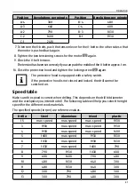
Page 21: ...s equipped with a safety switch If the protective hood is not closed and locked the drill cannot be switched on Speed table Make sure the speed is correct when drilling This depends on the drill bit d...

Page 22: ...ling may result in severe injury Never attempt to hold the workpiece with your hands Always clamp the workpiece in the enclosed vice If the workpiece cannot be clamped in the vice it is too large and...

Page 23: ...crew for setting the incline again Setting the drill depth You can set the desired drill depth with the scale ring 1 Switch the drill off push the red off switch O 31 and pull the mains plug out of th...

Page 24: ...hether the chuck key has been removed The chuck key if it becomes projectile may inflict serious injury Keep your hands away from the work area Never attempt to remove drill chips while a drill bit or...

Page 25: ...handle fixture 5 on one of the handles 6 anticlockwise to lower Turn it until the drill bit tool penetrates the workpiece to the desired depth 5 Then guide the handle in the opposite direction up to t...

Page 26: ...k to break the chips and release the tool again If a piece breaks off when working on the workpiece switch off the drill and pull the mains plug out of the socket Use pliers to help remove the fragmen...

Page 27: ...the tool 4 Remove the chips and other parts with a brush or similar 5 Clean the drill with a damp soft cloth You can use a mild soap for dirt that sticks to the device 6 Let all parts dry completely...

Page 28: ...before you put it into storage see chapter Cleaning 2 If possible store the clean drill and the accessories in the original packaging 3 Make sure that the storage room should is not accessible for ch...

Page 29: ...e tool is not suitable and or is not in good order and condition Use a suitable drill bit a suitable tool The right speed has not been selected Set the correct speed Technical data Model WZ TB 13 L Ar...

Page 30: ...ld affect the respective immission level present at the workplace involve the specification of the work area the surrounding area the duration of exposure other noise sources etc You must also observe...

Page 31: ...s substances that are frequently contained in waste electronic equipment incorrect handling of waste equipment may have a negative impact on the environment and on the health of human beings By dispos...

Page 32: ...uje zgodno wymienionego poni ej artyku u z nast puj cymi normami na podstawie dyrektywy WE BG LV paskaidro du atbilst bu ES direkt vai un standartiem LT apib dina atitikim EU reikalavimams ir prek s n...

Page 33: ...e within its intended use over the course of the first 3 years after date of purchase we will remedy the problem as quickly as possible once it has been brought to our attention In the unlikely event...

Reviews: