


IN
S
TA
LL
AT
IO
N
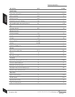
INSTALLATION & SERVICING INSTRUCTIONS FOR WORCESTER BOSCH
18
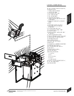
PIPEWORK POSITIONS &
FLUE OPENING
PIPEWORK POSITIONS &
FLUE OPENING
8-716-106-256a (08.05)
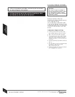
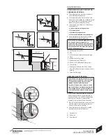
CAUTION: Ensure there are no pipes,
electric cables, damp proof course or other
hazards before drilling.
SAFETY:
All relevant safety precautions must be undertaken.
Protective clothing, footwear, gloves and safety
goggles must be worn as appropriate.
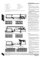
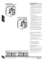
PIPEWORK POSITIONS:
A to D (opposite) show the pipe positions from the
front of the boiler:
A - CH flow/heating vent 1''Ø BSP
B - Primary drain/cold feed 1''Ø BSP
C - CH return 22mmØ copper
D - Flue outlet
E - Condensate outlet 21.5mmØ
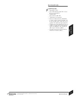
NOTE: For servicing purposes, keep the condensate
and pressure relief discharge pipes away from
components and pipework connections.
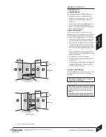
FLUE OPENING:
Follow the diagram opposite to mark the centre
of the flue (1, & 2) for rear opening, (2 & 3) for
side opening or (1 & 4) for top opening.
** IMPORTANT: for horizontal flues, increase
this height by 52mm for every 1000mm of
horizontal length that the flue opening is
away from the boiler
NOTE: all horizontal flue sections must rise away
from the boiler by 52mm per metre to ensure that
condensate flows back into the boiler for safe
discharge via the condensate waste pipe.
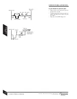
Make an opening (F, G or H) through the wall
using a core drill or similar at a size relative to
the wall thickness as shown below:
125mmØ flue:
Wall thickness
Flue hole size
150 - 240mm
155mmØ
240 - 330mm
160mmØ
330 - 420mm
165mmØ
420 - 500mm
170mmØ
Clear away any debris.
H
F
F
G
H
G
B
105
190
All dimensions in mm
105
185
105
500
67
752
C
D
550
25
C
D
A
B
A
B
A
2
1
3
752**
+5
4
412
E