Supplied By www.heating spares.co Tel. 0161 620 6677
15
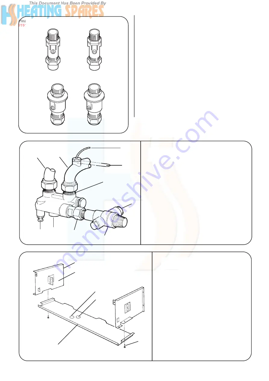
Fig 26-Service Valve Operation
Fig 28-Casing Bottom Panel Fixing
Fig 27-Relief Valve
COLD
WATER
INLET
CH
FLOW
&
RETURN
OPEN
CLOSED
OPEN
CLOSED
9
10
1
2
6
5
4
3
1. Flow/Return Manifold
2. Discharge Pipe Connection
3. Relief Valve
4. Relief Valve Union Connection
5. Bypass Adjuster
6. Drain Point
7. Central Heating Flow
8. Central Heating Return
9. Pressure Gauge Capillary
10. Capillary Clip
1. Control Panel Side Support
2. In-line Connector Bracket
3. Drain Access Opening
4. Bypass Adjuster Access
5. Bottom Panel Fixing Screw (2)
6. Bottom Panel
11.7.6. Check that the gas and water valves are closed. Refer to
Fig 26.
11.7.7. Lift the appliance onto the wall mounting plate/manifold
assembly ensuring that the connections fully enter the manifold
fittings after it is supported at the top.
11.7.8. Secure the gas and water connections.
11.7.9. Fit a discharge pipe to the relief valve leading it away
from any electrics or where it might be a hazard. The pipe must
not be less than 15mm in diameter and must run continuously
downward outside the appliance. Refer to Fig 27.
11.7.10. Remove the support brackets and fit the cabinet
bottom panel. Refer to Fig 21.
11.8.
Measure and cut the air and flue ducts
11.8.1. Measure the distance from the appliance. Refer to
Fig 29,30.
11.8.2. Add the following distances onto the measurements.
Rear: Air duct length
=
W + 65mm
Flue duct length
=
W + 105mm
Side: Air duct length
=
L + 15mm
Flue duct length
=
L + 142mm
7
8
1
2
3
4
6
5


