background image

UK/IE

INSTRUCTION MANUAL

INSTALLATION, COMMISSIONING & SERVICING

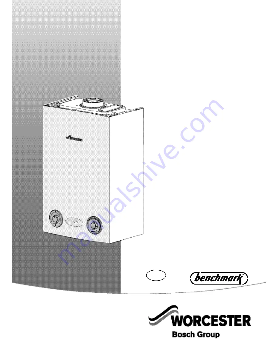
WALL HUNG RSF GAS FIRED CONDENSING BOILER

FOR OPEN VENTED AND SEALED CENTRAL HEATING SYSTEMS AND

INDIRECT MAINS FED DOMESTIC HOT WATER

THIS BOILER IS USED WITH

NATURAL GAS OR LPG (Cat II 2H3P TYPE C13, C33 & C53)

NATURAL GAS

12 Ri GC NUMBER: 41 311 63

15 Ri GC NUMBER: 41 311 75

18 Ri GC NUMBER: 41 311 77

24 Ri  GC NUMBER: 41 311 65

LIQUID PETROLEUM GAS

12 Ri  GC NUMBER: 41 311 64

15 Ri  GC NUMBER: 41 311 76

18 Ri  GC NUMBER: 41 311 78

24 Ri  GC NUMBER: 41 311 66

GREENSTAR 12Ri, 15Ri, 18Ri & 24Ri

Summary of Contents for Greenstar 12Ri

Page 1: ...INS FED DOMESTIC HOT WATER THIS BOILER IS USED WITH NATURAL GAS OR LPG Cat II 2H3P TYPE C13 C33 C53 NATURAL GAS 12 Ri GC NUMBER 41 311 63 15 Ri GC NUMBER 41 311 75 18 Ri GC NUMBER 41 311 77 24 Ri GC N...

Page 2: ...IS 813 EIRE ONLY AND THE USER MANUAL WITH THE OWNER OR AT THE GAS METER AFTER INSTALLATION OR SERVIC ING THE BENCHMARK CHECKLIST CAN BE FOUND IN THE BACK TWO PAGES OF THE INSTALLATION MANUAL ABBREVIAT...

Page 3: ...POSITION OF WIRED COMPONENTS 25 COMMISSIONING PRE COMMISSIONING CHECKS 26 FILLING THE SYSTEM 27 STARTING THE APPLIANCE 28 WATER TREATMENT 29 COMMISSIONING 30 FINISHING COMMISSIONING 31 SERVICING SPAR...

Page 4: ...st complete the Service Record on the Benchmark Checklist after each service Current Gas Safety Installation Use Regulations All gas appliances must be installed by a competent person in accordance wi...

Page 5: ...ator CH temperature sensor control External pump anti seizure protection Flue gas temperature limiter Condensate trap syphon 590mm 390mm A B C D E 270mm GENERAL INFORMATION INSTALLATION SERVICING INST...

Page 6: ...79 64 Flue Gas Temp 40 30 C rated min load C 41 33 44 33 48 34 54 35 43 35 46 36 49 37 55 38 CO2 level at max rated heat output after 30 mins 9 8 9 8 9 8 9 8 11 0 11 0 11 0 11 0 CO2 level at min rated...

Page 7: ...ERMOSTAT 16 FLAME VIEWING MIRROR REPLACED BY RETAINING BRACKET ON LATER APPLIANCES 17 SECURING NUT AIR GAS MANIFOLD CLAMP 18 SENSOR BOILER FLOW 19 FLUE AIR PRESSURE SWITCH CONNECTION 20 FLUE OVERHEAT...

Page 8: ...SOFTENED WATER MUST NOT BE USED TO FILL THE CENTRAL HEATING SYSTEM Fill the system with cold water and check for leaks Open all drain cocks and drain the system Close drain cocks and add a suitable f...

Page 9: ...ly by the gas supplier to ensure it is in good working order and can meet the gas flow and pressure requirements in addition to the demand from any other appliance being served This does not include t...

Page 10: ...Y plan system as one of the ports is open to flow A Static Head Minimum static head 250mm measured from the highest point in the heating system top surface of the appliance or highest point in the hea...

Page 11: ...ust be a minimum of 22 mm plastic pipe The condensate pipework must fall at least 50 mm per metre towards the outlet and should take the shortest practicable route The pipework must follow one of the...

Page 12: ...e NOTE These are the combined left right clearances excluding the appliance BOILER LOCATION CLEARANCES SERVICING CLEARANCES VENTED COMPARTMENT Using 100mm flue kit 980mm Using 125mm flue kit 1010mm VE...

Page 13: ...168a 06 2008 11 PRE INSTALLATION BATHROOMS The boiler must be installed outside the shaded areas shown opposite Additional RCD Residual Current Device pro tection may be required Refer to the latest...

Page 14: ...ite Use the fittings supplied in the Lit Hardware pack If the flow and return pipes are to be run behind the appliance it maybe an advantage to connect the pipes before hanging on the wall especially...

Page 15: ...total flue length 100mm 125mm 12 Ri 4 400mm 13 000mm 15 Ri 4 400mm 13 000mm 18 Ri 4 400mm 13 000mm 24 Ri 4 400mm 13 000mm Maximum total flue length 100mm 125mm 12 Ri 2 400mm 11 000mm 15 Ri 2 400mm 11...

Page 16: ...densation will be discharged from the flue outlet Where this could be a nuisance for example near security lighting an alter nate position should be found The air inlet outlet duct and the terminal of...

Page 17: ...FLUE TERMINAL POSITIONS INSTALLATION SERVICING INSTRUCTIONS FOR WORCESTER GREENSTAR Ri 8 716 115 168a 06 2008 15 FLUE TERMINAL POSITIONS PRE INSTALLATION...

Page 18: ...observed Additional requirements for roof space installation The boiler should be first unpacked before ascending ladder to loft space Two sets of steps should be used Two people should share the lif...

Page 19: ...d 1 If a 100mm diameter flue is to be used a125mm diameter hole is required However if using the weather sealing collar by pushing it through from inside the property then a 150mm diameter hole is req...

Page 20: ...e 2 captive screws B securing boiler casing at the bottom of the appliance 3 Pull case upwards 4 Remove cardboard packing piece from appliance With the outer case removed the appliance is suitable for...

Page 21: ...OTE If pipes require reducing in length this is best done before they are fitted to the boiler Lift the boiler onto the wall plate and level using the feet D at the bottom rear of the boiler casing Fi...

Page 22: ...A by withdrawing from tube B to achieve the flue length required between 350 570mm NOTE Ensure that the TOP label of both sections are aligned before securing the two parts at the required length The...

Page 23: ...to the boiler flue outlet F For ease of assembly locate screw H first and then fit screws D to secure flue turret E If fitting from the outside of the building slide the outer wall seal C onto the ter...

Page 24: ...Remove the 3 inner flue tube retaining screws The inner tube will be held in place in the appliance Fit turret onto appliance and retain with the three removed screws NOTE The clamping plate flat sho...

Page 25: ...condensate drain is 22mm diameter plastic pipe It must fall at least 50mm per metre towards the outlet NOTE Do not use solvents adhesive or lubricant when pushing the pipe onto the rubber connector A...

Page 26: ...mmet in the main crossbar marked mains cable and through the cable clamp C ensure there is ample cable to reach the connectors 7 Turn cable clamping screw D clockwise to secure cable and replace clamp...

Page 27: ...NTS COMMISSIONING PUMP N PUMP L 2 orange 2 violet 2 blue 2 red green DIAGNOSTIC INTERFACE L N INSTALLATION SERVICING INSTRUCTIONS FOR WORCESTER GREENSTAR Ri 8 716 115 168a 06 2008 25 POSITION OF WIRED...

Page 28: ...eck the gas pipework connections and rectify any leaks NOTE Do not use solvents adhesive or lubricant when pushing the pipe onto the rubber connector 3 Check that the condensate pipe D has been connec...

Page 29: ...directed away from the fan or any other electrical component to prevent any water damage Also place a suitable cover over the fan to prevent any spillage of water onto electrical connections Ensure t...

Page 30: ...lluminates GREEN 4 If the boiler fails to light and the boiler goes to flame lock out the BLUE power indicator B will flash To reset the lockout turn the boiler thermostat control to minimum then past...

Page 31: ...mpatible with aluminium The pH value of the system water must be less than 8 or the appliance guarantee will be invalidated If connected to an open vent system turn on the water supply to the system h...

Page 32: ...t point and connect a manometer Measure the pressure with the boiler running at maximum Check the gas supply working pressure at the gas valve inlet point is no less than N G 18 5 mbar L P G 37 mbar E...

Page 33: ...ce outer casing Replace outer casing making sure that the securing points are properly located Replace top two screws D Re tighten bottom two screws E HANDOVER Complete the Benchmark Gas Boiler Commis...

Page 34: ...ervice space around the appliance is clear Refer to page 11 for information 3 Check all the joints and connections in the system and remake any that show signs of leakage Refill and re pressurise if a...

Page 35: ...remove It is necessary to remove bottom tray if action 2 to 2 2 is done this is retained by two screws at the front and hooks over the bottom frame work of the boiler 2 Adjusting boiler control to se...

Page 36: ...o Maximum 1 Remove the three screws A retaining the control cover Clipped inside the cover is a plastic tool used to change the mode switch setting B 2 Using the tool set the mode switch to maximum En...

Page 37: ...ve Syphon The syphon body is opaque so that contents can be examined Empty the contents and flush with clean water COMBUSTION TESTING MUST BE CARRIED OUT BY A COMPETENT PERSON IT MUST NOT BE ATTEMPTED...

Page 38: ...of the heat exchanger until it stops at the lug Lift up assembly and remove from boiler 7 Disconnect spark electrode and flame sensor connections K Remove clamping plate L Remove spark flame electrode...

Page 39: ...affle O and the top baffle N are refitted correctly When re fitting the burner ensure that it fits centrally within the heat exchanger and location tabs are situated in location holes Ensure seal is r...

Page 40: ...h and the boiler will stay in this mode for 15 minutes if no further change is made to the switch MAX NORM MIN THE BOILER IS FACTORY SET ADJUSTMENT OF AIR GAS RATIO IS ONLY REQUIRED IF STATED IN THE S...

Page 41: ...able above If required adjust D on the gas valve until the correct measurement is set Remove brass dust cap with flat bladed screwdriver Then using a 4mm allen key adjust CO CO2 Replace dust cap Check...

Page 42: ...asure the CO CO2 and check against the table above If required adjust D on the gas valve until the correct measurement is set Using a 2mm hexagonal ball driver adjust the CO CO2 Check CO is less than...

Page 43: ...ulling upwards Squeeze retaining clip on plastic moulding D and pull sensor E upwards until clear of pocket in heat exchanger Coat new sensor with heat conductive paste and replace 3 Overheat thermost...

Page 44: ...t of boiler Disconnect electrical connections Replace valve with new seals and check for gas soundness Note The valve will require setting follow procedure Setting the air gas ratio 7 Syphon 7 1 Undo...

Page 45: ...trol Remove 4 screws C retaining the rear panel of the control and remove panel IMPORTANT ENSURE CODE PLUG IS RE FITTED TO THE NEW CONTROL IF THIS IS NOT DONE THE APPLIANCE WILL INDICATE ERROR AND WIL...

Page 46: ...etaining pressure switch to bracket Refit new pressure switch to bracket NOTE After re assembly check CO CO2 levels as described in the setting of the air gas ratio section REPLACEMENT OF PARTS The fo...

Page 47: ...eat exchanger Remove burner G Replace new burner in correct position Ensure that burner tab fits correctly into hole NOTE After re assembly check CO CO2 levels as described in the setting of the air g...

Page 48: ...5 Control primary temperature sensor Worcester Part No 8 716 106 688 0 GC No H26 542 6 Pressure switch Worcester Part No 8 716 106 633 0 GC No H26 543 7 Overheat thermostat heat exchanger Worcester P...

Page 49: ...ol box and replace with new one from LPG conversion kit Reassemble control box and replace outer case For code plug numbers see table at the foot of the page CAUTION TURN OFF THE GAS SUPPLY AND ISOLAT...

Page 50: ...out reset 15 ST9 connector 16 Flame sense electrode Pin 1 green 17 Primary NTC sensor Pin 4 red Pin 5 red 18 Solenoid valve 1 Pin 6 blue Pin 7 blue 19 Solenoid valve 2 Pin 8 violet Pin 9 violet 20 Flu...

Page 51: ...trol board Blockage in flue system Temperature sensor 8000 20000 Wiring connections to sensor Fan cable connections Code plug fitted Service mode switch in min position Service mode switch in max posi...

Page 52: ...as modulation to achieve set temperature 35 82 C END OF BOILER DEMAND Gas valve OFF Pump run 3 minutes Fan run 30 seconds Over temperature shut down if water tempera ture is 5 C above set value Fan ov...

Page 53: ......

Page 54: ......

Page 55: ......

Page 56: ...e air inlet Boiler noisy or going to overheat 1 Check that the primary flow left hand pipe from the boiler is hotter than the primary return right hand pipe If the return is hotter than the flow then...

Reviews: