CASCADE FRAME INSTALLATION
6 720 648 720 (2011/07)
10
5
CASCADE FRAME INSTALLATION
B
Fix the frame onto the first leg of the cascade unit.
Use the M8 x 70 screws for this.
B
Now fix the next leg and continue fitting until the
cascade unit is compelte.
B
Position the frame into its final position.
B
Adjust the frame so that it is in the right position and
so that it is level both horizontally and vertically. Fit
additional washers under the leg until level.
B
Secure the frame to the floor. Ensure bolts are aligned
to the legs. Do not bend or place the leg under stress
to make it fit.
B
Install the main gas pipe. Use the M8 x 70 screws for
this. Do not fully tighten the screws yet.
B
Install the header pipe. Use the M8 x 70 screws for
this. Do not fully tighten the screws yet.
B
Fit the boiler mounting brackets on the top of the
frame. Install the nuts at the rear of the frame. The
underside of the bracket should be level with the
underside of the frame. Use the M8 x 65 screws for
this.
5.1
BOILER ASSEMBLY AND PUMP
GROUP INSTALLATION
B
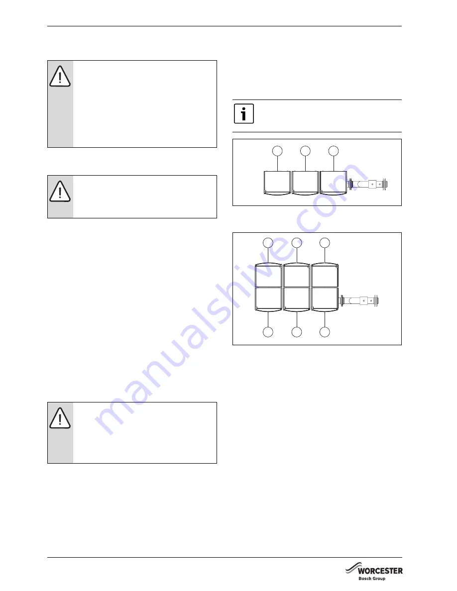
Hang the first boiler on the cascade frame as shown
in fig. 7 or fig. 8.
Fig. 7
Installation sequence for a TL-inline
configuration
Fig. 8
Installation sequence for TR-back-to-back
configuration
B
Put the boiler in the correct position and level it hori-
zontally and vertically. Use the set screws on the
lower rear of the boiler to adjust it.
B
Connect the pump group (
Æ
GB162 Installation and
service instructions).
B
Remove the protective yellow caps from the main gas
pipe.
B
Apply PTFE tape to the screw thread connections.
B
Connect up the gas connection pipe between the gas
valve and the main gas pipe. Use PTFE tape to create
a perfect seal.
B
Remove the protective caps from the header.
B
Remove all red paint and unevenness from the flow
and return connections of the header.
B
Install the flow pipe(s) between the header and the
pump group.
B
Install the return pipe(s) between the header and the
pump group.
CAUTION:
B
Make sure that the surface the cascade
system is to be installed on is flat.
B
Use a spirit level when installing the cas-
cade system.
B
Check that the load-bearing capacity of
the floor is sufficient for the weight of the
installation (approx. 100 kg for each boil-
er with accessories).
CAUTION:
Make sure that the slots for the boiler
mounting bracket are at the top of the
frame.
CAUTION:
For TR-back-to-back configurations, both
boiler mounting brackets are fitted
simultaneously, using the same screws.
Only use M8 x 65 screws to secure the
mounting brackets.
You must observe the installation sequence
indicated in fig. 7 and fig. 8 when installing
the boilers.
3
1
2
7214 6000-007.1TD
2
4
6
5
3
1
7214 6000-00
8
.1TD


