Woodstock Shop Fox W1669 Instruction Manual Download Page 15

-13-

Drill.Chuck.and.

Spindle

Your keyed drill chuck attaches to the drill 

spindle. When properly joined, the JT-33 

tapers on the spindle and inside the chuck cre-

ate an almost permanent connection. 

To.install.the.drill.chuck,.do.these.steps:

1...

Clean the drill chuck and spindle with min-

eral spirits and follow all safety warnings 

on the container (see 

Figure.17

).


Note

: Failure to clean the tapered mating 

surfaces of the spindle and drill chuck may 

result in a loose or wobbly chuck.
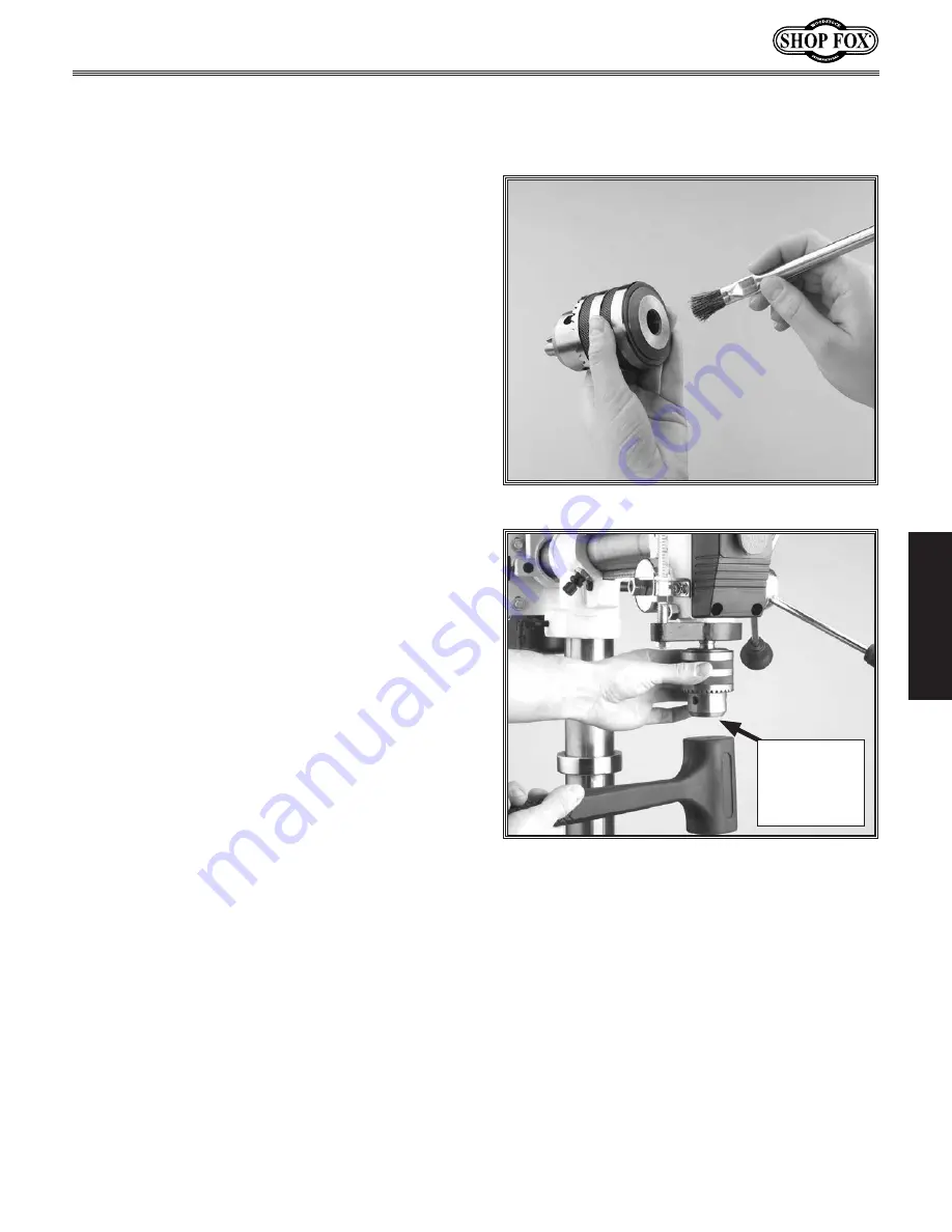
2.

  Use the provided chuck key to adjust the 

jaws of the chuck until they are inside of 

the drill chuck body (see 

Figure.18

). 

3.

  Place the drill chuck on the spindle and tap 

the chuck onto the spindle with a block of 

wood or a dead-blow hammer (see 

Figure.

18

). 

DO.NOT.

use a metal hammer to seat 

the drill chuck onto the spindle!

Figure.18..

Seating chuck into spindle.

Figure.17..

Clean the chuck before installation.

Chuck Jaws 

Recessed and 

Protected 

Inside of 

Chuck

ASSEMBLY

Summary of Contents for Shop Fox W1669

Page 1: ...opfox biz COPYRIGHT DECEMBER 2003 BY WOODSTOCK INTERNATIONAL INC REVISED MARCH 2018 HE WARNING NO PORTION OF THIS MANUAL MAY BE REPRODUCED IN ANY SHAPE OR FORM WITHOUT THE WRITTEN APPROVAL OF WOODSTOC...

Page 2: ...ls are Lead from lead based paints Crystalline silica from bricks cement and other masonry products Arsenic and chromium from chemically treated lumber Your risk from these exposures varies depending...

Page 3: ...ASSEMBLY 8 Base and Column 9 Table Support 10 Headstock 12 Drill Chuck and 13 Spindle 13 ADJUSTMENTS 14 Belt Tension 14 Feed Shaft Spring Tension 15 Quill Shaft Screw 16 Table 17 OPERATIONS 18 Test Ru...

Page 4: ...committed to customer satisfaction in providing this manual It is our intent to make sure all the information necessary for safety ease of assembly practical use and dura bility of this product be inc...

Page 5: ...to Base W1669 15 1 2 W1670 49 Maximum Distance Spindle to Table W1669 9 1 4 W1670 31 1 2 Overall Height W1669 31 1 2 W1670 64 1 2 Head Tilt 45 Left 90 Right Table Tilt 90 Left and Right Table Rotation...

Page 6: ...et or open flame environ ments Airborne dust particles could cause an explosion and severe fire hazard 6 Ensure all guards are securely in place and in working condition 7 Make sure switch is in the O...

Page 7: ...l do a safer and better job at the rate for which it was designed 13 Use correct tool DO NOT force machine or attachment to do a job for which it was not designed 14 Wear proper apparel DO NOT wear lo...

Page 8: ...er drill while holding the workpiece by hand Figure 2 Keep fingers away from spinning drill bits cutters and sanding surfaces Figure 3 Remove switch safety key when not in use 6 Avoiding Potential Inj...

Page 9: ...ols at the same time will add to the electrical load being applied by the drill press Add up the load ratings of all machines on the circuit If this number exceeds the rating of the circuit breaker or...

Page 10: ...low and Figure 5 to inventory your shipment before beginning assembly If any parts are missing call Woodstock International Inc at 360 734 3482 or tech support shopfox biz While the main components of...

Page 11: ...press base drill the plywood c Secure the base to the plywood with four 3 8 diameter bolts washers and nuts not included If installing the W1669 to a tool table or workbench do these steps a Position...

Page 12: ...side exactly three turns 2 Starting with the pinion gear insert the shaft into the table bracket and mesh the teeth with the worm gear as shown in Figure 9 3 Align the set screw in the crank handle wi...

Page 13: ...l the rack tapered point seats into the bevel see Figure 13 10 Position the column ring so the table bracket and rack can just rotate around the column without binding 11 Carefully snug the set screw...

Page 14: ...see Figure 14 2 With an assistant lift and position the headstock pocket over the column and allow the headstock to slide down until the column fully seats into the headstock approximately 2 see Figu...

Page 15: ...to clean the tapered mating surfaces of the spindle and drill chuck may result in a loose or wobbly chuck 2 Use the provided chuck key to adjust the jaws of the chuck until they are inside of the dri...

Page 16: ...r in position and tighten the lock screw and make sure the belt deflec tion gap is correct when pinched together between the pulleys see Figure 21 If the gap between both inner sides of the belt is gr...

Page 17: ...rom spinning see Figure 22 3 Make sure the quill is completely seated and the depth stop reads zero 4 Put on thick leather gloves and hold the spring cover against the side of the head stock so the co...

Page 18: ...as it can go with out binding the quill 5 Tighten the jam nut and check the quill movement for binding or play while moving the quill up and down through its entire range of travel 6 Re adjust the qu...

Page 19: ...w 5 Turn the index pin draw nut clockwise and draw the index pin out of the casting until you can rotate the table to your desired angle see Figure 29 Note Use this index pin only for indexing the tab...

Page 20: ...ers and lock handles are tight 3 Make sure the drill chuck key is removed 4 Plug in the power cord 5 Lift the ON OFF switch to start the drill press and make sure that your fingers are poised near the...

Page 21: ...31 To use the headstock tilting feature do these steps Note If the scale is not calibrated set the table to zero degrees zero the headstock with the table and then reposition the scale to zero degree...

Page 22: ...aws instead of only two and NEVER allow a chuck to grab the fluted body of drill bits 4 Using any of the three key locations tighten the chuck with the chuck key and remove the key see Figure 34 Figur...

Page 23: ...lock knob when the right tension is achieved 6 Close the cover UNPLUG the drill press before changing speeds to avoid accidental start up Failure to do this may result in serious personal injury The M...

Page 24: ...y When the hex nuts are set the nuts will contact the stop flange and stop the drill press from drilling any deeper To adjust the drilling depth do these steps 1 Measure the maximum depth that you wan...

Page 25: ...Drill Cutter and Hole Saw Suggested RPM Chart 23 OPERATIONS...

Page 26: ...24 OPERATIONS...

Page 27: ...eriodic maintenance on your Model W1669 and W1670 Radial Drill Press will ensure its opti mum performance Make a habit of inspecting your drill press after each use Check for the following conditions...

Page 28: ...oting MAINTENANCE This section covers the most common symptoms and corrections with this type of machine WARNING DO NOT make any adjustments until power is disconnected and moving parts have come to a...

Page 29: ...chine and wall receptacle before doing any electrical service Otherwise you or others may be burned or electrocuted resulting in injury or death Start Capacitor Capacitor Cover 110V Motor Start Switch...

Page 30: ...56 49 76 53 21 26 62 25 35 52 63 10 77 81 9 30 8 85 86 24 88 87 76 0 1 2 3 15 94 103 79 38 1 89 35 1 19 4 19 1 19 2 19 3 45A 3 45A 1 45A 2 16A 1 16A 11 19 6 19 5 32 1 107 107 105 104 107 106 108 89 3...

Page 31: ...69045A 2 DEPTH STOP ROD BRACKET 45A 3 X1668031A 6 DEPTH STOP MOUNT 46 X1668030 FEED SHAFT 47 X1668033 FEED COLLAR 48 X1669048 HANDLE 49 X1669049 DEGREE SCALE 50 XPR03M EXT RETAINING RING 12M 51 XP6201...

Page 32: ...30 1 3 4 5 83 84 78 79 71 73 74 70 72 80 73 7 Mounting Surface 98 93 13 91 99 7 2 84 1 56 11 11 7 1 W1669 Parts MAINTENANCE...

Page 33: ...N BRKT 54 XPS07 PHLP SCREW 1 4 20 X 3 8 56 X1669056 RIVET 70 X1669070 PIN 71 X1669071 WORM PINION REF PART DESCRIPTION 72 X1669072 LIFT HANDLE CRANK 73 XPSS01M SET SCREW M6 1 0 X 10 74 X1669074 10T GE...

Page 34: ...32 1 71 73 74 70 72 4A 84 94 95 96 97 11 11 84A 80 73 7 3 Mounting Surface 98 93 13 83 5A 101 92 56 7 2 7 3 84 1 7 1 W1670 Parts MAINTENANCE...

Page 35: ...0 X1668010A 3 AXLE 71 X1668012 WORM PINION 72 X1668016 LIFT HANDLE 73 XPSS01M SET SCREW M6 1 0 X 10 REF PART DESCRIPTION 74 X1668015 WORM GEAR 80 X1668008 COLUMN RING 83 X1670083 TABLE 84 X1668010A 1...

Page 36: ...ealer in your area these products are also available through online dealers Please call or e mail Woodstock International Inc Customer Service to get a current listing of dealers at 1 800 840 8420 or...

Page 37: ...shank 5 16 drill center point and hex wrench D3161 Steelex Heavy Duty Carbide Tipped Adjustable Circle Cutter is Carbide Tipped and cuts 13 4 to 53 4 diameter holes in the toughest material For use w...

Page 38: ...36 Notes...

Page 39: ...Notes 37...

Page 40: ...auses not within the scope of Woodstock International Inc s warranty then the original owner must bear the cost of storing and returning the product This is Woodstock International Inc s sole written...

Page 41: ..._ Yes _____ No 5 Would you recommend Shop Fox products to a friend ______ Yes _____ No 6 What is your age group ______ 20 29 ______ 30 39 _____ 40 49 ______ 50 59 ______ 60 69 _____ 70 7 What is your...

Page 42: ...TAPE ALONG EDGES PLEASE DO NOT STAPLE FOLD ALONG DOTTED LINE FOLD ALONG DOTTED LINE WOODSTOCK INTERNATIONAL INC P O BOX 2309 BELLINGHAM WA 98227 2309 Place Stamp Here...

Page 43: ......

Page 44: ......

Reviews: