background image

30 | GB

•  Loosen the lock nut (27a) and adjust the adjustment 

screw (27) until the angle between the saw blade 

(6) and the rotary table (14) is precisely 45°.

•  Re-tighten the lock nut (27a).

•  Subsequently check the position of the angle indi-

cator. If necessary, loosen the pointer (19) using a 

Philips screwdriver, set to position 45° on the angle 

scale (18) and re-tighten the retaining screw.

8.6  Mitre cut 0°- 45° and turntable 0° (fig. 1/2/11)

The crosscut, drag and mitre saw can be used to 

make mitre cuts of 0° - 45° in relation to the work face.

Attention! For mitre cuts (inclined saw head), the 

left 

side

 of the moveable stop rails (16a) must be fixed in 

the outer position.

•  Open the set screw (16b) for the moveable stop rail 

(16a) and push the moveable stop rail (16a) out-

wards.

• 

The  moveable  stop  rail  (16a)  must  be  fixed  far 

enough in front of the innermost position that the 

distance between the stop rail (16a) and the saw 

blade (6) amounts to a minimum of 8 mm.

•  The 

right side

 of the moveable stop rails (16a) 

must be in the inner positiion.

•  Before making a cut, check that the stop rail (16a) 

and the saw blade (6) cannot collide.

•  Secure the set screw (16b) again.

•  Move the machine head (4) to the top position.

•  Fix the rotary table (14) in the 0° position.

•  Loosen the set screw (22) and use the handle (1) 

to angle the machine head (4) to the left, until the 

pointer (19) indicates the desired angle measure-

ment on the scale (18).

•  Re-tighten the set screw (22).

•  Cut as described in section 8.3.

8.7  Mitre cut 0°- 45° and turntable 0°- 45°  

(fig. 2/4/12)

The crosscut, drag and mitre saw can be used to 

make mitre cuts to the left of 0°- 45° in relation to the 

work face and, at the same time, 0° - 45° to the left or 

0° - 45° to the right in relation to the stop rail (double 

mitre cut).

Attention! For mitre cuts (inclined saw head), the 

left 

side

 of the moveable stop rails (16a) must be fixed in 

the outer position.

•  Open the set screw (16b) for the moveable stop rail 

(16a) and push the moveable stop rail (16a) out-

wards.

• 

The  moveable  stop  rail  (16a)  must  be  fixed  far 

enough in front of the innermost position that the 

distance between the stop rail (16a) and the saw 

blade (6) amounts to a minimum of 8 mm.

•  Before making a cut, check that the stop rail (16a) 

and the saw blade (6) cannot collide.

•  Re-tighten the set screw (16b).

•  Move the machine head (4) to its upper position.

Attention!

 The machine executes an upward stroke 

automatically due to the return spring, i.e. do not 

release the handle (1) after completing the cut; in-

stead allow the machine head to move upwards 

slowly whilst applying light counter pressure.

8.4 Crosscut 90° and turntable 0° - 45° (fig. 1/7/8)

The crosscut, drag and mitre saw can be used to 

make crosscuts of 0° -45° to the left and 0° -45° to the 

right in relation to the stop rail.

Important! For 90° crosscuts, the moveable stop rail 

(16a) must be fixed in the inner position.

•  Open the set screw (16b) for the moveable stop 

rail (16a) and push the moveable stop rail (16a) in-

wards.

• 

The  moveable  stop  rail  (16a)  must  be  fixed  far 

enough in front of the innermost position that the 

distance between the stop rail (16a) and the saw 

blade (6) amounts to a minimum of 8 mm.

•  Before making the cut, check that the stop rail (16a) 

and the saw blade (6) cannot collide.

•  Secure the set screw (16b) again.

•  Loosen the handle (11) if tightened, pull up the 

latched  position  lever  (35)  with  your  index  finger 

and use the handle (11) to set the rotary table (14) 

to the desired angle.

•  The pointer (12) on the rotary table must match the 

desired  angle  on  the  scale  (13)  on  the  fixed  saw 

table (15).

•  Re-tighten the handle (11) to secure the rotary table 

(14).

•  Cut as described under section 8.3.

8.5   Precision adjustment of the stop for mitre cut 

45° (fig. 1/2/5/9/10)

•  No stop angle included.

•  Lower the machine head (4) and secure it using the 

locking bolt (23).

•  Fix the rotary table (14) in the 0° position.

Attention! For mitre cuts (inclined saw head), the 

left 

side

 of the moveable stop rails (16a) must be fixed in 

the outer position.

•  Open the set screw (16b) for the moveable stop rail 

(16a) and push the moveable stop rail (16a) out-

wards.

• 

The  moveable  stop  rail  (16a)  must  be  fixed  far 

enough in front of the innermost position that the 

distance between the stop rail (16a) and the saw 

blade (6) amounts to a maximum of 8 mm.

•  The 

right side

 of the moveable stop rails (16a) 

must be in the inner positiion.

•  Before making a cut, check that the stop rail (16a) 

and the saw blade (6) cannot collide.

•  Loosen the set screw (22) and use the handle (1) to 

angle the machine head (4) 45° to the left.

•  45° - position angle stop (B) between the saw blade 

(6) and rotary table (14).

Summary of Contents for SL90LXU

Page 1: ...eitung 5 GB Sliding cross cut mitre saw Translation of the original instruction manual 21 Art Nr 3901226901 AusgabeNr 3901226850 Rev Nr 12 08 2020 Nachdrucke auch auszugsweise bed rfen der Genehmigung...

Page 2: ...2 2 4 5 23 23 11 36 21 22 27a 26a 19 18 20 7a 27 22 26 37 D 1 1 10 2 4 5 13 14 15 16 17 7 11 8 9 3 16a 35 16b 6 3 24 25 33 24a 3 24 25 24a 3...

Page 3: ...3 9 20 C C 26 27 22 8 8 4 14 7 13 7 6 16a max 8 mm 6 19 18 14 6 A 13 24 24a 25 10 6 B 14 11 12 4 4 7 7 14 14 max 8 mm 1 7 4 3 14 5a...

Page 4: ...4 21 22 17 20 E E E 19 32 32a 32b 32b 16 17 18 15 5 29 34 31 33 30 28 C 6...

Page 5: ...edienungsanleitung und Sicherheitshinweise lesen und beachten Schutzbrille tragen Geh rschutz tragen Bei Staubentwicklung Atemschutz tragen Achtung Verletzungsgefahr Nicht in das laufende S geblatt gr...

Page 6: ...ferumfang 8 4 Bestimmungsgem e Verwendung 8 5 Sicherheitshinweise 8 6 Technische Daten 13 7 Vor Inbetriebnahme 13 8 Aufbau und Bedienung 14 9 Transport 17 10 Wartung 17 11 Lagerung 18 12 Elektrischer...

Page 7: ...eses Ger t entstehen bei unsachgem er Behandlung Nichtbeachtung der Bedienungsanweisung Reparaturen durch Dritte nicht autorisierte Fach kr fte Einbau und Austausch von nicht originalen Ersatz teilen...

Page 8: ...7 vormontiert 2 x Werkst ckauflage 8 vormontiert Sp nefangsack 17 Innensechskantschl ssel 6 mm C Innensechskantschl ssel 3 mm D S geblatt Betriebsanleitung 4 Bestimmungsgem e Verwendung Die Kapp und Z...

Page 9: ...ung des Elektrowerk zeuges a berlasten Sie das Ger t nicht Verwenden Sie f r Ihre Arbeit das daf r be stimmte Elektrowerkzeug Mit dem passenden Elektrowerkzeug arbeiten Sie besser und siche rer im ang...

Page 10: ...Sie nie die Hand ber die vorgese hene Schnittlinie weder vor noch hinter dem S geblatt Abst tzen des Werkst cks mit ge kreuzten H nden d h Halten des Werkst cks rechts neben dem S geblatt mit der link...

Page 11: ...er f Greifen Sie bei rotierendem S geblatt nicht hinter den Anschlag Unterschreiten Sie nie einen Sicherheitsabstand von 100 mm zwi schen Hand und rotierendem S geblatt gilt auf beiden Seiten des S ge...

Page 12: ...nd Zugs ge benutzen 5 Verwenden Sie ausschlie lich S gebl tter die f r den zu schneidenden Werkstoff geeignet sind 6 Verwenden Sie nur die vom Hersteller festgeleg ten S gebl tter Die S gebl tter m ss...

Page 13: ...ungsge fahr Restrisiken k nnen minimiert werden wenn die Wichtige Hinweise und die Bestimmungsgem e Verwendung sowie die Bedienungsanweisung insge samt beachtet werden Belasten Sie die Maschine nicht...

Page 14: ...n schlagschienen 16a und dem S geblatt 6 keine Kollision m glich ist Feststellschrauben 16b wieder anziehen Maschinenkopf 4 in die obere Position bringen Die Maschine muss standsicher aufgestellt wer...

Page 15: ...fixiert werden Linke Seite Maschinenkopf 4 am Handgriff 1 nach hinten schieben und gegebenenfalls in dieser Position fi xieren je nach Schnittbreite Legen Sie das zu schneidende Holz an die An schlag...

Page 16: ...ehen Nach max einer Umdrehung rastet die S gewel lensperre 30 ein ffnen Sie die Feststellschraube 16b der ver schiebbaren Anschlagschienen 16a und schieben Sie die verschiebbaren Anschlagschienen 16a...

Page 17: ...er ein Jetzt mit etwas mehr Kraftaufwand Flanschschrau be 28 im Uhrzeigersinn l sen Flanschschraube 28 ganz heraus drehen und Au enflansch 29 abnehmen Das S geblatt 6 vom Innenflansch 31 abneh men und...

Page 18: ...oder in der Gemeindeverwaltung nach Service Informationen Es ist zu beachten dass bei diesem Produkt folgen de Teile einem gebrauchsgem en oder nat rlichen Verschlei unterliegen bzw folgende Teile al...

Page 19: ...g M gliche Ursache Abhilfe Motor funktioniert nicht Motor Kabel oder Stecker defekt Netzsi cherungen durchgebrannt Maschine vom Fachmann berpr fen lassen Nie Motor selbst reparieren Gefahr Netzsicheru...

Page 20: ...20 DE...

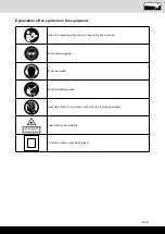
Page 21: ...nt Read the operating instructions to reduce the risk of inquiry Wear safety goggles Wear ear muffs Wear a breathing mask Important Risk of injury Never reach into the running saw blade Important Lase...

Page 22: ...Scope of delivery 24 4 Intended use 24 5 Safety information 24 6 Technical data 28 7 Before starting the equipment 28 8 Attachment and operation 29 9 Transport 31 10 Maintenance 32 11 Storage 32 12 El...

Page 23: ...device does not assume liability for damages to the product or damages caused by the product that occurs due to Improper handling Non compliance of the operating instructions Repairs by third parties...

Page 24: ...isted cables increase the risk of electric shock 3 Scope of delivery Crosscut drag and mitre saw 1 x Clamping device 7 preassembled 2 x Workpiece support 8 preassembled Sawdust bag 17 Allen key 6 mm C...

Page 25: ...he safety of the power tool e When working outdoors with power tools only use extension cords which are suited for outdoor areas Using extension cords suited for outdoor applica tions reduces the risk...

Page 26: ...sing the blade to bite and pull the work with your hand into the blade p Let the blade reach full speed before contact ing the workpiece This will reduce the risk of the workpiece being thrown Warning...

Page 27: ...and disconnect the plug from the power source and or remove the battery pack Then work to free the jammed material Contin ued sawing with a jammed workpiece could cause loss of control or damage to t...

Page 28: ...om pletely and secure it with an Allen key D All covers and safety devices have to be properly fitted before the equipment is switched on It must be possible for the blade to run freely Furthermore de...

Page 29: ...pressure Now push the machine head 4 slowly and steadily to the very back until the saw blade 6 has completely cut through the work piece When the cutting operation is completed move the machine head...

Page 30: ...hat the stop rail 16a and the saw blade 6 cannot collide Re tighten the set screw 16b Move the machine head 4 to its upper position Attention The machine executes an upward stroke automatically due to...

Page 31: ...se the rotary table 14 by loosening the han dle 11 Using the handle 11 set the rotary table 14 to the desired angle refer also to point 8 4 in this regard Re tighten the handle 11 to secure the rotary...

Page 32: ...connection cables have been cut due to being driven over Insulation damage due to being ripped out of the wall outlet Cracks due to the insulation ageing 10 Maintenance m Warning Prior to any adjustm...

Page 33: ...ts accessories are made of various types of material such as metal and plastic Defective com ponents must be disposed of as special waste Ask your dealer or your local council Old devices must not be...

Page 34: ...ive noise Coils damaged motor defective Arrange for inspection of the motor by a special ist The motor does not reach its full power Circuits in the network are overloaded lamps other motors etc Do no...

Page 35: ...35...

Page 36: ...2014 29 EU 2014 35 EU X 2014 30 EU 2004 22 EC 2014 68 EU X 2011 65 EU 89 686 EC_96 58 EC 90 396 EC Der oben beschriebene Gegenstand der Erkl rung erf llt die Vorschriften der Richtlinie 2011 65 EU des...

Page 37: ...este plazo se torne in til a causa de fallas de material o de fabricaci n Las piezas que no son fabri cadas por nosotros mismos ser n garantizadas hasta el punto que nos corresponda garant a del sumin...

Page 38: ...eg d t jiem Jauno deta u uzst d anas izmaksas ir j uz emas pirc jam Pirkuma atcel ana vai pirkuma cenas samazin ana k ar jebkuras citas pras bas par boj jumu atl dzin anu netiek izskat tas Garantija L...

Reviews: