


BA_WP_KSM9-3000-200-3100-150_EN_22-22.docx
41
14
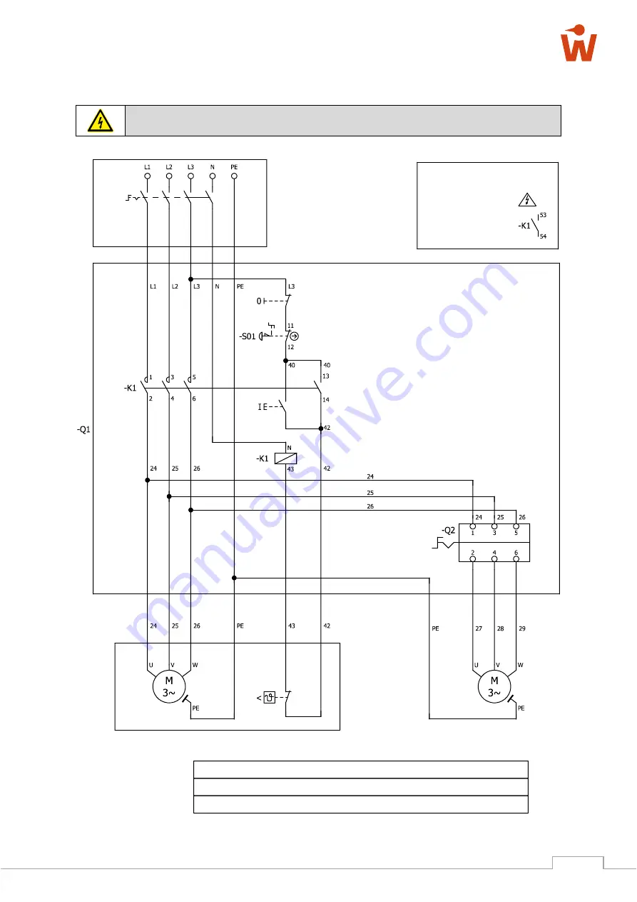
Electrical Circuit Diagram
Work on the electrical components of the machine may only be carried out by an authorised
electrician!
Figure 47: Electrical circuit diagram
Motor M1 - 4.0 kW
Motor M2 - 0.25 kW
OPTION
BMK
Indication
Type
Manufacturer Art. No.
Quantity
-S01
E-STOP combination
CEPY1-2001
ABB
4079.0071.
1
-K1
Auxiliary switch block 1S, 1Ö
LA1KN11
Schneider
4078.0132
1
E-STOP
Attention!
External voltage!
Units are energised
even when the main
switch is turned off!
Auxiliary contact for on-site extraction
Main switch
Off
On


