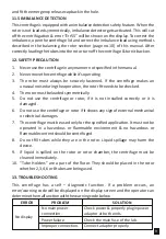
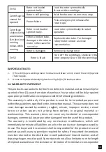
background image

6.1 Connec ng Power Adaptor

1.  Connect one side of power adaptor to rear side of centrifuge and other to 

supply as shown in the figure below.

2.  Rotate clockwise the adaptor nut to  ghten the adaptor with the centrifuge. 

Ensure the power switch is OFF while connec ng the power adaptor.

3.  The s cker on the body & jack are indica ng the posi on of the rib on the jack. 

While  fi ng  the  adaptor  to  the  unit  please  match  the  s cker  posi on  as 
shown in the figure below & gently push it in.

4.  If matched correctly the plug will go in easily without much force (do not try 

to force the plug in if it is not matched properly). Once the plug is inserted into 
posi on,  turn  the  loose  upper  ring  clockwise  to  ghten  &  to  secure  the 
fitment.

7. STANDARD PARTS LISTING

2

1

3

Match the 

rib and slot 

Match the 

sticker 

1. View Window 
2. Groove to open the lid 
3.Operation  and  setting 
Buttons
4. Display
5. Emergency Lid Release

1. Power Switch
2. Adaptor Port

Rear View

Rubber Mount/
Base Mount

1
2

Front View

2

3

4

5

1

Bottom view

3

Summary of Contents for Clinispin CT25

Page 1: ...Clinispin CT25 User Manual...

Page 2: ......

Page 3: ...1 4 TechnicalSpeci ca on 1 5 StandardAccessories 2 6 Installa on 2 7 StandardPartsLis ng 3 8 TubeHolder Adaptors 4 9 RotorInstalla on 6 10 BalancingtheRotor 6 11 Opera on 7 12 SafetyPrecau on 9 13 Tr...

Page 4: ...ancedetectorwithautocut o forsafeopera on Brushless DC motorformaintenancefreeperformance Lidlocksafety thelidopensautoma callyonruncomple on Digitaldisplaywithspeedand meindicator RPM se ngfrom500 65...

Page 5: ...the packaging and accessories are removed from the rotor chamber The rotor is pre installed Pleasemakesurethatrotoris rmly ghtened Accessoriesanduser manual are kept inside the box with the centrifug...

Page 6: ...lease match the s cker posi on as showninthe gurebelow gentlypushitin 4 If matched correctly the plug will go in easily without much force do not try toforcethepluginifitisnotmatchedproperly Oncethepl...

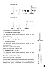
Page 7: ...ps three di erent reduced adaptor can be designed to hold di erent types of blood collec ontubes The di erent adaptor combina ons along with tube holder for di erent blood collec ontubesareillustrated...

Page 8: ...R C The maximum diameter and proposed length for such combina onare MaximumTubeDiameter 13mm ProposedTubeLength 55to75mm Check both the criteria Max Diameter Proposed Length of the blood collec on tub...

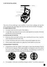
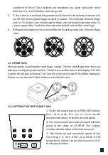
Page 9: ...clean Load the rotorver callyintothemotorsha 2 PuttheT Allenkeyintherotornut turnclockwiseto ghtentherotor 3 A erproperlyfasteningtherotor placetheTubeHoldersintotherotor 10 BALANCING THE ROTOR 1 Alwa...

Page 10: ...operly installing the centrifuge switch ON the centrifuge from the rear sidebypressingthepowerswitch Thelidstatuswillbeseeninthedisplay Ifthelid isopen thedisplaywillshow Lid andifitisclosed theset RP...

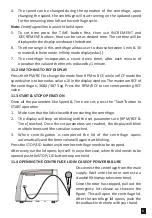
Page 11: ...e RPM RCF to see corresponding RCF value 11 3 START STOP OPERATION Once all the parameters like Speed Time are set press the Start bu on to START opera on 1 Makesurethatthelidisclosedbeforestar ngthec...

Page 12: ...r rotor if it is not installed correctly or it is damaged 6 Do not use the centrifuge or rotor if it shows any sign of external mechanical orelectricaldamages 7 The centrifuge must be used only for th...

Page 13: ...te all liabili es on us for the products or damages caused by its use The buyer and its customer shall be responsible for the product or use of products as well as any supervision required for safety...

Page 14: ...amage We will not be responsible for damage incurred byimproperpackaging All items returned for service should be set postage prepaid in the original packaging or other suitable carton added to avoid...

Page 15: ......

Page 16: ...ngdom Tel 44 0 8456 777001 Fax 44 0 8456 777002 enquiries woodleyequipment com Woodley Equipment Company Inc USA O ce 37 18 Northern Boulevard STE 512 Long Island City NY 11101 United States Toll Free...

Reviews: