background image

SETUP & OPERATION

Blade Height Adjustment

2

2-3

ISHdoc063008

SETUP & OPERATION

2.3

Blade Height Adjustment

The LTAGA-PLCBN sharpener is equipped with a blade height adjustment assembly that
allows smooth height adjustment of 1”, 1 1/4”, 1 1/2”, 1 3/4" and 2" wide blades. 

To install the blade, release the blade clamp by pushing the clamp handle down.

See Figure 2-2. 

Position the blade on the cylindrical rollers of the blade height

adjustment screws as shown below. Use the blade height adjustment knob to adjust the
blade height. 

NOTE:


After adjusting the blade height, adjust the blade support arms in the vertical

plane as necessary so the blade will remain level around its complete length.

FIG. 2-2

Blade Height 

Adjustment Knob

Blade

Cylindrical 

Roller

Blade Height 

Adjustment 

Screw

Blade Clamp 

Handle

Summary of Contents for LTAGA-PLCBN

Page 1: ...R Safety Operation Maintenance Parts Manual 097032 rev A 00 Safety is our 1 concern Read and understand all safety information and instructions before oper ating setting up or maintaining this machine August 2001 Form 944 ...

Page 2: ...UP OPERATION 2 1 2 1 Machine Start 2 1 2 2 Blade Support Installation 2 2 2 3 Blade Height Adjustment 2 3 2 4 Sharpener Alignment 2 4 2 5 Grinding Wheel Installation 2 6 2 6 Blade Installation 2 7 2 7 Face Grind Adjustment 2 9 2 8 Grind Depth Adjustment 2 12 2 9 Oil Flow Adjustment 2 13 2 10 Feed Rate Adjustment 2 13 2 11 Magnetic Shut off 2 13 2 12 Blade Rejection 2 14 2 13 Operation Overview 2 1...

Page 3: ...ort Assembly 6 2 6 3 Grinder Asembly 6 3 6 4 Sharpener Mounting Plate 6 5 6 5 Blade Clamp Assembly 6 6 6 6 Oil Pump Pan 6 8 6 7 Cam Assembly 6 9 6 8 Cover Assembly 6 11 6 9 Alignment tool 6 12 SECTION 7 ELECTRICAL INFORMATION 7 1 7 1 Electrical Symbol Diagram 7 1 7 2 Electrical Component List 7 2 7 3 Component Layout Diagram 7 2 ...

Page 4: ...Kolo Poland at 48 63 2626000 Wood Mizer will accept the folowing methods of payment Visa Mastercard or Select Purchase COD Prepayment Net 15 with approved credit Be aware that shipping and handling charges may apply Handling charges are based on size and quantity of order In most cases items will ship on the day they are ordered Second Day and Next Day shipping are available at additional cost ...

Page 5: ...of your equipment He also can schedule you for a service call Office Hours All times are Eastern Standard Time IMPORTANT Read the entire Operator s Manual before operating the conveyor Take notice of all safety warnings throughout this manual and those posted on the equipment Keep this manual with this equipment at all times regardless of ownership Wood Mizer is a registered trademark of Wood Mize...

Page 6: ... operating this equipment and observe all safety warnings Warning stripes are placed on areas where a single decal would be insufficient To avoid serious injury keep out of the path of any equipment marked with warning stripes Read and observe all safety instructions before operating this equipment Also read any additional manufacturer s manuals and observe any applicable safety instructions inclu...

Page 7: ...LTAGE can cause shock burns or death SHUT OFF LOCK OUT POWER before performing service in any area of this machine DO NOT restore power until all access panels are replaced and secured WARNING Always turn off and disconnect power at control console AND at main supply circuit breaker before performing any service to the machine 1 2 Blade Handling WARNING Always wear gloves and eye protection when h...

Page 8: ...in serious injury DANGER Always keep hands away from moving bandsaw blade Failure to do so will result in serious injury WARNING Always wear eye ear respiration and foot protection when operating this machine Failure to do so may result in serious injury WARNING Secure all loose clothing and jewelry before operating this machine Failure to do so may result in serious injury or death WARNING The sh...

Page 9: ...The LTAGA PLCBN sharpener is designed for sharpening only Wood Mizer blades with 9 29 10 30 13 29 and 4 32 profiles See Figure 1 1 The major components of the sharpener are shown below FIG 1 1 CBNSH03C Blade Support Arms Cam Index Assembly Grinder Assembly Sharpener Head Clamp Assembly Oil Pan Filter Magnets Control Box ...

Page 10: ...e 1 1 The overall dimensions and the weight of the PLCBN sharpener without the blade support arms are listed below See Figure 1 2 The figure below shows the overall dimensions of the PLCBN sharpener with the blade support arms installed Model Length Width Height Weight Weight of sharpener packaged in carton LTAGA PLCBN 627mm 845mm 590mm 83kg 90kg TABLE 1 1 FIG 1 2 CBNSH36B ...

Page 11: ...e levels it is not possible to determine with certainty if preventives are needed or are not needed The factors affecting a current level of noise exposure during work are inter alia room characteristics and characteristics of other noise sources e g number of machines and machining operations nearby Also the permissible exposure level value may vary depending on country This information enables t...

Page 12: ...ety General Information 1 9 Control Panel Components See Figure 1 3 The control panel components and their descriptions are shown below FIG 1 3 Feed Rate Dial Emergency Stop Disconnect Switch Cam Motor Start Stop Switch Grinder Motor Stop Switch Coolant Pump Start Stop Switch ...

Page 13: ... or decrease cam speed Grinder Motor Start Stop Switch Starts Stops grinder motor Cam Motor Start Stop Button Press the Cam Motor Start Switch to start the cam motor NOTE Place the Feed Rate Dial in the 0 position before starting the cam motor Press the Cam Motor Stop Switch to turn the cam motor off and unclamp the blade Coolant Pump Start Stop Switch Starts Stops coolant pump Emergency Stop Stop...

Page 14: ...g Decals Description See Table 1 5 The pictographic decals that warn and inform the user are shown and described below TABLE 1 5 Decal View Decal No Description S10364 P2 Hazardous voltage 086362 General warning symbol 099220 CAUTION Close all guards and covers before starting the machine S10364 P2 086362 099220 ...

Page 15: ...tion Safety General Information ISHdoc063008 1 10 1 095961 Use ACP 1 oil S12004G 1 CAUTION Always wear safety goggles when operating the sharpener S20097C 2800 RPM Motor rotation direction P85070 CE safety certification TABLE 1 5 095961 O I L A C P 1 ...

Page 16: ...s located in the foot plates The sharpener can be operated with a oil vapors exhaust system only The machine can be operated under roof only The sharpener can be operated only in temperature range from 5o C to 40o C at the humidity of up to 80 The oil for cooling the grinding wheel must meet the specifications listed in Table 1 4 on page 9 Water or other liquids must not be used The position of th...

Page 17: ...pport without post two bolts a self locking nut and a wing nut See Figure 2 1 To install the guides join one guide assembly around the end of each blade support arm Face the post outward as shown Bolt from the hexed side of the guide assembly these hex shaped holes will keep the bolts from turning once in place Secure the top bolt with a self locking nut Secure the bottom bolt with a wing nut 2 Ti...

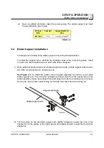
Page 18: ...blade clamp by pushing the clamp handle down See Figure 2 2 Position the blade on the cylindrical rollers of the blade height adjustment screws as shown below Use the blade height adjustment knob to adjust the blade height NOTE After adjusting the blade height adjust the blade support arms in the vertical plane as necessary so the blade will remain level around its complete length FIG 2 2 Blade He...

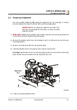
Page 19: ...ANT Make sure the grinder motor is OFF Cycle the cam until the grinding wheel is at the tip of the tooth about to begin face grind 2 Remove the grinding wheel cover and sharpener arbor nut Dismount the oiler Remove the grinding wheel 3 Remove the blade rest bolts and moving clamp plate 4 Install the alignment tool to the grinder motor shaft as shown below See Figure 2 3 Position the tool so all th...

Page 20: ...three tool gauge points Secure in position by tightening the clamp adjustment bolts See Figure 2 4 7 Remove the arbor nut and alignment tool 8 Reinstall the moving clamp plate 9 Reinstall the grinding wheel and secure in place with the arbor nut 10 Mount the oiler Reinstall the grinding wheel cover FIG 2 4 CBNSH09C Clamp Adjustment Bolts ...

Page 21: ...in place and secured before operating the sharpener Failure to do so may result in serious injury Also check that the grinding wheel does not contact the oiler If it does contact adjust the oiler out of the way The gap between the grinding wheel and the oiler should be 5 1 mm 8 If the installed grinding wheel is running out axially unscrew the arbor nut turn the grinding wheel about 15 degrees and...

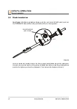
Page 22: ...n the FEED RATE dial until the cam pivot bolt is at the 2 o clock position Uncoil a blade and position above the three support assemblies around the sharpener Check to be sure the teeth on the portion of blade that will be under the grinding wheel point to the right as you face the sharpener If not remove the blade and invert it FIG 2 5 CBNSH10 Cam Pivot bolt at 2 o clock ...

Page 23: ... Then raise and hold the indexing arm up loosen the blade clamping fixture and press the blade between the clamping plates Lower the indexing arm and the sharpener head Make final adjustments to the blade support arms and guide assemblies Make sure the blade band rests evenly on both blade rest bolts The blade should not touch the bottom of either side guide assembly All three guide assemblies sho...

Page 24: ...the tooth face is ground lighter or heavier 1 Before adjusting the face grind make sure the cam and grinder motors are off the feed rate dial is set at 0 and the Sharpener head is raised 2 Install the blade 3 Turn on the cam motor and slowly increase the FEED RATE until the next tooth is underneath the grinding wheel 4 Lower the Sharpener head and check to make sure the grinding wheel lightly cont...

Page 25: ...SETUP OPERATION Face Grind Adjustment SETUP OPERATION ISHdoc063008 2 10 2 FIG 2 8 CBNSH11 Face Grind Adjustment Knob ...

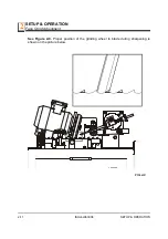
Page 26: ...SETUP OPERATION Face Grind Adjustment 2 2 11 ISHdoc063008 SETUP OPERATION See Figure 2 9 Proper position of the grinding wheel to blade during sharpening is shown on the picture below FIG 2 9 CBNSH37B ...

Page 27: ...at controls how far the grinding head comes down and therefore controls the gullet grind See Figure 2 10 CAUTION The grind depth adjustment bolt is factory set and should not need to be readjusted The gullet grind should be adjusted by setting the blade height with the blade height adjustment knob See Section 2 3 NOTE Depth grind may be affected as the grinding wheel passes over blade welds FIG 2 ...

Page 28: ...by maintenance to a maximum speed of 60 revolutions per minute See Section 4 2 2 11 Magnetic Shut off See Figure 2 10 The shut off sensor is located to the right of the blade clamp assembly When passed over by a magnet it automatically shuts down the grinder and cam motors To install take an orange painted magnet from the bag assembly Place the black side of the magnet against the bottom edge of t...

Page 29: ... over stressed and will fold on itself the blade is missing 2 or 3 teeth or more in a row the blade band has been twisted the blade band is too low for the grinder the blade has been sharpened too many times too much material has already been ground from the blade the blade has no set on one of its sides severe rust is present or the blade has tooth spacing uncommon to Wood Mizer blades i e a comp...

Page 30: ...If a heavy grind is required it is best to go around the blade lightly twice rather than try to grind heavily once 6 After about ten teeth have been ground mount the orange painted magnet right behind the blade wiper See Section 2 11 7 Check the depth grind two to three times during the blade sharpening Adjust as necessary IMPORTANT After any adjustment always restart the blade and sharpen in its ...

Page 31: ...e blades NOTE The grinding wheels have a CBN Cubic Boran Nitride coating 1 To replace shut down and lock out all power to the machine 2 Remove the grinding wheel cover 3 Remove the grinding wheel nut washer plate and grinding wheel 4 Install the new grinding wheel Reinstall the washer plate and nut 5 Reinstall the grinding wheel cover 3 2 Oil Level Periodically check the oil level and refill with ...

Page 32: ... clamp the blade firmly To do so unscrew the blade rest bolts and remove the moving clamp plate Clean sediment from the oil pan and filter magnets as needed Keep the oil at such a level that the pump strainer is completely covered with the oil Replace the oil completely every six months Dispose of worn out oil in compliance with applicable regulations Check the axial run out and the radial run out...

Page 33: ...hat would otherwise have to be scraped off when it dries Wipe with a clean dry rag Make sure the flow of oil through the oiler assembly is strong Sharpen the blade when it first shows signs of dullness If the blade is extremely dull due to hitting a rock or some form of foreign matter sharpen the blade twice lightly instead of trying to remove too much in one grind Grinding too much material at on...

Page 34: ...5 5 1 ISHdoc063008 Alignment SECTION 5 ALIGNMENT Align the sharpener monthly to ensure quality performance Also realign the sharpener as necessary i e after the grinding wheel has been impacted by the index pawl ...

Page 35: ... A03333 Subassembly K05555 includes parts M06666 and F07777 77 The diamond indicates M06666 is not available except in subassembly K05555 To Order Parts From Europe call our European Headquarters and Manufacturing Facility in Kolo Poland at 48 63 2626000 From the continental U S call our toll free Parts hotline at 1 800 448 7881 Have your customer number vehicle identification number and part numb...

Page 36: ...ts Replacement Parts Blade Support Assembly 6 6 2 Blade Support Assembly REF DESCRIPTION Indicates Parts Available In Assemblies Only PART QTY 1 BLADE SUPPORT ASSEMBLY COMPLETE 087518 1 3 1 GUIDE KIT BLADE SUPPORT A10617 1 CBNSH20 1 2 ...

Page 37: ...0 1 Wheel 10 30 LTAGA Grinding CBN Profile 030381 1 1 Wheel 13 29 LTAGA Grinding CBN Profile 030389 1 Wheel 4 32 LTAGA Grinding CBN Profile 050145 1 4 Washer M12 Flat Zinc F81056 1 1 5 Nut M12x1 25 8 Hex Zinc F81034 8 1 6 Cover Front Guard 088247 1 1 7 Screw M6x16 DIN 316 Thumb F81001 16 2 8 Screw M5x25 8 8 Hex Socket Head Cap Zinc F81000 7 4 9 Washer 10 2 Split Lock Zinc F81055 2 1 10 Bolt M16x50...

Page 38: ...bow 088379 1 20 Bushing Sharpener Vertical Pivot 088339 1 1 21 Bearing w Ring 086395 2 22 Bushing Sharpener Head Spacer 092672 1 23 Washer 17 Flat Zinc F81058 1 1 24 Screw 12 M10x16 12 9 Bossard Socket Head Shoulder F81003 64 1 25 Pin 5x16 Roll Fe Zn Zinc F81044 3 1 26 Bolt M8x50 8 8 Hex Head Full Thread Zinc F81002 19 1 27 Nut M8 Hexagon Grade 5 8 Free Zinc F81032 1 1 28 Base Weldment Sharpener H...

Page 39: ...T M10 8 B FE F81033 3 3 6 FOOT BASE ADJUST 092839 2 7 NUT 10MM X 1 25 NYLON F81033 6 2 8 SEAL RUBBER WIRE INSIDE DIA 26MM 085613 1 9 BOLT M6X16 8 8 HEX HEAD FULL THREAD ZINC F81001 15 6 10 WASHER 6 4 FLAT ZINC F81053 1 6 11 BOLT M10X25 8 8 FE ZN5 F81003 11 1 BRACKET CBN AC COVER WELDMENT 087824 1 12 Bracket Cover Weldment 087826 1 1 13 Bumper Cover Bracket 087825 1 14 Bolt M6x30 5 8 Hex Zinc F8100...

Page 40: ... ZINC PLATED 096865 1 2 5 BLOCK THREADED ZINC PLATED 096866 1 1 6 SCREW BLADE HEIGHT ADJUSTMENT DRIVING ZINC PLATED 096867 1 1 7 SPROCKET 05B 1 Z20 8x3 12H7 ZINC PLATED 098513 1 3 8 PIN 4X30 SPRING TYPE STRAIGHT ZINC PLATE F81044 7 3 CHAIN BLADE HEIGHT ADJUSTMENT COMPLETE 098515 1 9 CHAIN 05B 1 73 DRIVING 098516 1 10 LINK QRC05B 1 MASTER 098517 1 11 SCREW 8 M6X30 12 9 SOCKET HEAD SHOULDER F081001 ...

Page 41: ...NUT M8 8 B HEX NYLON ZINC LOCK F81032 2 2 23 BRACKET BLADE CLAMP SPRING 097069 1 1 24 BOLT M8X20 5 8 HEX HEAD FULL THREAD ZINC F81002 1 1 25 SPRING 087376 1 26 STUD BOLT 1M10X90 8 8 FE ZN5 F81003 85 1 27 GRIP L70 THREAD M10 13870M10 089445 1 COMPLETE BLADE WIPER 098526 1 28 BRACKET WELDMENT BLADE WIPER MOUNT 092770 1 1 29 BOLT M8X20 5 8 HEX HEAD FULL THREAD ZINC F81002 1 2 30 WASHER 8 4 FLAT ZINC ...

Page 42: ...TO SHARPENER COOLANT P09836 1 2 PAN SHARPENER OIL 088201 1 3 HANDLE 4 W BOLTS P08065 1 4 BOLT 8 32X3 8 F05018 5 2 5 MAGNET OIL FILTER P31347 2 6 BOX CBN SHARPENER CONTROL 092628 1 7 SCREW M6X20 10 9 FE ZN5 DIN 7991 F81001 17 2 8 WASHER 6 5 FLAT ZINC F81053 11 2 9 NUT M6 8 B HEX NYLON ZINC LOCK F81031 2 2 10 DECAL OIL PICTOGRAM 095961 1 1 2 3 5 6 CBNSH24B 7 4 8 9 10 ...

Page 43: ...ARING 6203 2RS 086114 2 3 SHAFT CAM DRIVE 087366 1 4 MOTOR 1 30HP 62RPM 12VDC 53 1 GEAR P09698 1 1 5 SNAP RING PN M 85111 F81090 21 1 6 CAM AGA PROFILE 010741 1 7 BEARING 608 2RS ROLLER 086197 2 8 WASHER 8 4 FLAT ZINC F81054 1 1 9 NUT M8 8 B HEX NYLON ZINC LOCK F81032 2 1 10 BLOCK INDEX ZINC 087373 1 1 1 2 3 4 5 6 7 8 9 10 11 21 22 13 12 14 15 16 15 17 18 19 20 23 24 25 26 28 27 29 30 31 34 32 33 ...

Page 44: ... 045E 12 P04734 1 29 SCREW M12x12 33H HEX SOCKET FLAT POINT F81004 15 1 30 GLAND NUT TRAILER HITCH DW 11 H 085388 1 31 BOLT M8 X 65MM HH GRADE 5 8 ZINC F81002 3 1 32 NUT M8 HEXAGON GRADE 5 8 FREE ZINC F81032 1 1 33 NUT M8 8 B HEX NYLON ZINC LOCK F81032 2 1 34 BOLT M12x40 8 8 HEX HEAD FULL THR ZINC F81004 4 2 35 WASHER 13 FLAT ZINC F81056 1 4 36 NUT M12 8 HEX NYLON ZINC LOCK F81034 2 2 COMPLETE CAM...

Page 45: ... Weldment 088254 1 1 2 Handle w Bolts P08065 1 3 Pipe Fume Exhaust Connection 087974 1 1 4 Bolt M6x16 8 8 Hex Head Full Thread Zinc F81001 15 4 5 Washer 6 4 Flat Zinc F81053 1 8 6 Nut M6 8 Hex Zinc F81031 1 4 7 DECAL GENERAL WARNING 086362 1 8 DECAL EYE WARNING SMALL S12004G 1 1 9 DECAL CLOSE ALL GUARDS BEFORE OPERATING 099220 1 10 DECAL CE CERTIFIED SAWMILL SAMLL P85070 1 1 2 3 5 4 6 CBNSH25 7 8 ...

Page 46: ...08 Replacement Parts Replacement Parts Alignment tool 6 6 9 Alignment Tool REF DESCRIPTION Indicates Parts Available In Assemblies Only PART QTY 1 ALIGNMENT TOOL 088382 1 2 Nut M6 8 B Hex Nylon Zinc Lock F81031 2 3 1 2 ...

Page 47: ...ELECTRICAL INFORMATION Electrical Symbol Diagram ELECTRICAL INFORMATION ISHdoc063008 7 1 7 SECTION 7 ELECTRICAL INFORMATION 7 1 Electrical Symbol Diagram FIG 7 1 XS M2 M2 M3 M3 M1 M1 BROWN WHITE BLUE ...

Page 48: ...C60N C10 24401 F2 Schneider 091457 Circuit Breaker C60N C4 24398 Tr BREVE 090988 Transformer TMM200 A 230 115 24 14 Pr 084318 Bridge Rectifier KBPC 3508 W S USA P03027 Grinder Motor Switch W P USA P03027 Coolant Pump Start Stop Switch M1 Besel 087769 Grinder Motor SEKg56 2C2 M2 USA P09836 Coolant Pump M3 USA P09698 1 Motor Cam Index R Hybryd 088837 Feed Rate Dial H166 1 Ps1 Ps2 Moeller 090452 Star...

Reviews: