


Setup & Operation
Cutting The Log
2
2-25
doc041118
Setup & Operation
2.15 Cutting The Log
The following steps guide you through normal operation of the Wood-Mizer sawmill.
1.
Once the log is placed where you want it and clamped firmly, turn the key switch to the accessory
(#2) position.
2.
Use the blade height scale to determine where to make your first cut
(
See Section 2.18
). The blade
height scale will help you to do this. Set the blade to the desired height with the up/down switch.
Make sure that the blade will clear all side supports and the clamp. Adjust the outer blade guide to
clear the widest section of the log by moving the blade guide toggle switch.
NOTE:
An optional laser sight is available to help determine where the blade will travel through the
log. See the laser sight manual for detailed operating instructions.
3.
Make sure all covers and guards are in place. Push the START button to start the blade spinning.
4.
Start the water lube if necessary to prevent sap buildup on the blade.
See Section 2.18
.
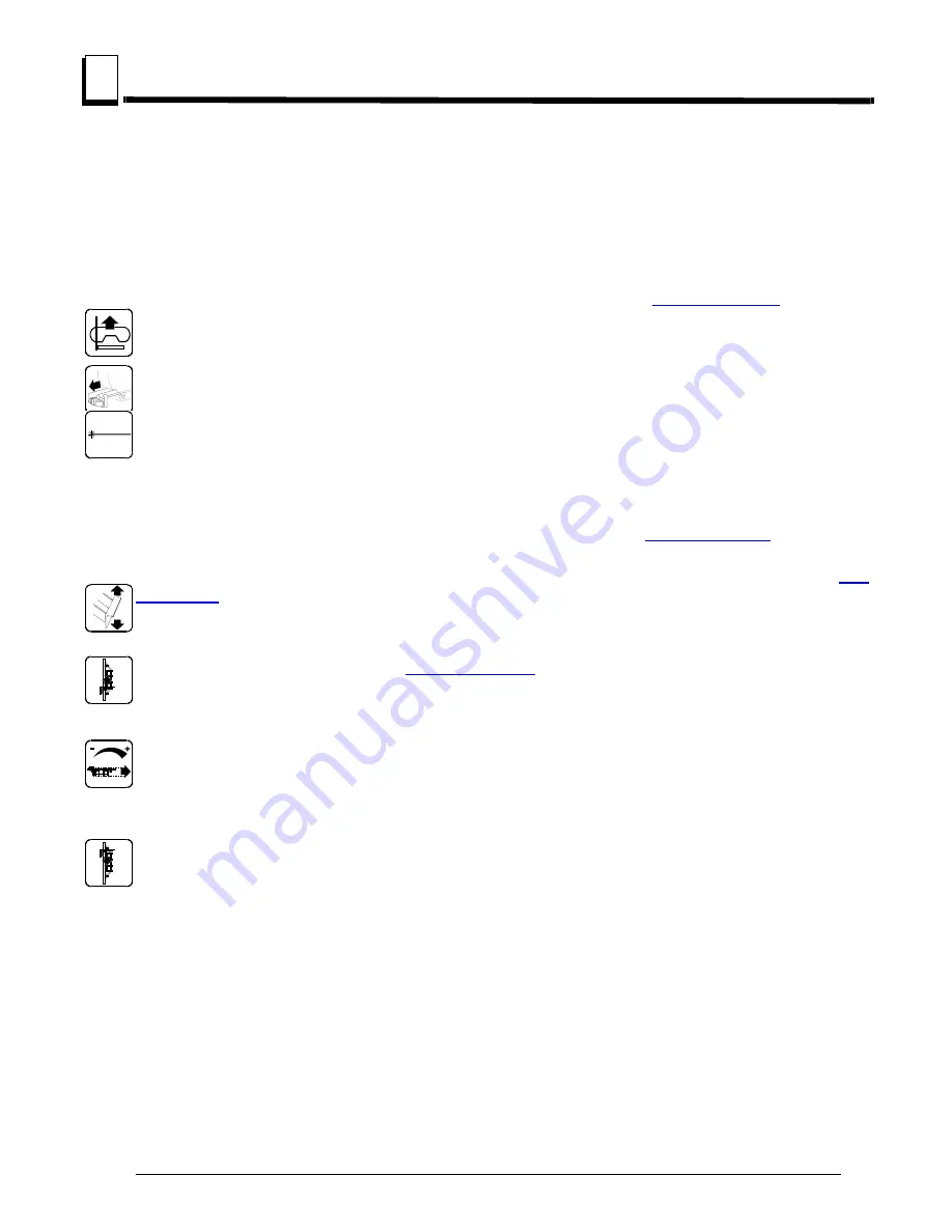
5.
If you want to use the board return function, push the toggle switch on the control panel down.
See
Section 2.8
.
6.
Feed the blade into the log slowly
(
See Section 2.13
).
Once the blade completely enters the log,
increase the feed rate as desired. Always try to cut at the fastest speed you can while keeping an
accurate cut. Cutting too slowly will waste blade life and lower production!
7.
As you get to the end of the log, slow down the feed rate. When the teeth exit the end of the log, turn
the feed rate all the way down. Push te STOP button to stop the motor. Remove the slab that you
have just cut from the log.
8.
Use the carriage forward/reverse switch to return the carriage to the front of the mill. Always
disengage the blade before returning the carriage for the next cut.
9.
Repeat until the first side of the log is cut as desired. Set aside the usable flitches (boards with bark
on one or both sides). You can edge them on the mill later.


