3200NT Timer
20
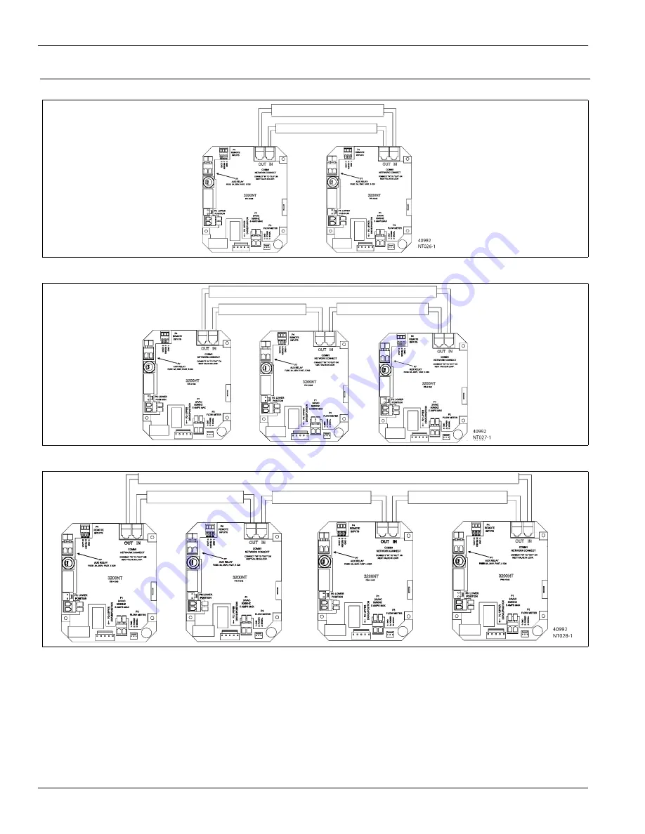
Network Timer System Configuration Wiring Diagrams
Two Timers
Three Timers
Four Timers
Interlocking
3200NT
NOTE:
Use only 6-place, 4-conductor, RJ11 phone or extension cables.
1.
Connect phone or extension cables first before programming.
— System Type 7 and 6: flow meter cable must be connected to the timer programmed as the LEAd Timer.
2.
A maximum cable length of 100’ cable can be used between timers.
3.
Always connect “IN” communication port to the “OUT” communication port of the next timer. Connect the last
timer back to the first timer.
Figure 8
: Network Timer System Wiring Diagram for System 5, 6, 7 and 9 Duplex
Figure 9
: Network Timer System Wiring Diagram for System 5, 6 and 9 Triplex
Figure 10
: Network Timer System Wiring Diagram for System 5, 6 and 9 Quadplex
Summary of Contents for 3200NT
Page 24: ...P N 41093 Rev B 02 04 ...


