24
72V Li-ION POWER 34-37-40
Intended use
EN
Intended use
The lawnmower is intended solely for the mowing of
lawns. Any other use is classed as an unintended
use.
The user is liable for any damages arising from
unintended use.
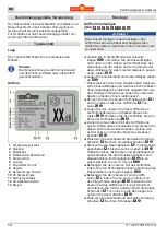
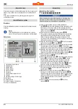
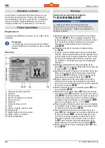
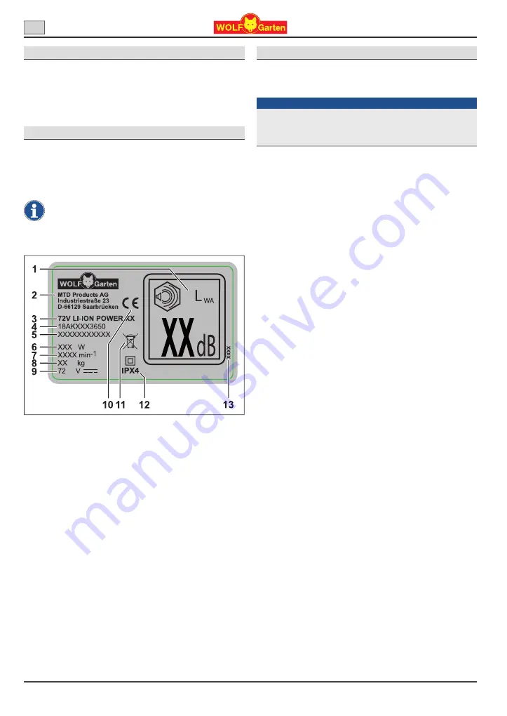
Identiication plate
Position
The identiication plate is located at the lawnmower
casing.
Note
The identiication is considered as a docu
‑
ment. It must never be altered or obliterated.
Structure
1
Guaranteed sound level
2
Manufacturer
3
Model name
4
Model number
5
Serial number
6
Capacity
7
Motor rotation speed in min
-1
8
Weight
9
Nominal voltage, Current type
10
CE label
11
Disposal note
12
Class / degree of protection
13
Year of manufacture
Assembly
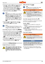
Attaching the handle
(Fig.
A B C D E F G H U
)
Attention !
When folding the handle together or folding the
handle out, the cable may be damaged. Ensure
that the cable is not kinked or squeezed.
Î
Grip in the handle recess of the delector
lap
B 1
and pull the delector lap upwards until
the hook on the rear side of the casing and the
hook on the underside of the delector lap engage
with a loud click
B 2
.
Î
Then lower the delector lap again
B 3
.
3
The grass is easily ejected through the resulting
gap between the delector lap and the casing
when mowing without the grass collector. You
can ind more information in the section “Mowing
without the grass collector”.
Î
Now ix both handle mountings
Ab
to the bottom
part of the handle
Ah
, see
C 1
.
Î
Attach the bottom part of the handle to the handle
mountings so that it clicks in
C 2
. Push the
handle up to the end of the handle mounting
C 3
.
Î
Slightly pull the bottom part of the handle apart at
its ends and push onto the threaded screws lo-
cated on the left and right side of the casing
D 1
.
Î
Then position the two washers
Ad
on the
threaded screws
D
2
.
Î
Push the threaded pins
Af
into the quick-release
levers
Aa
, until the hole is visible
E 1
. Hold
these tightly with inger and thumb and screw
in the quick-release levers together with the
threaded pins in a clockwise direction
E 2
until
there is a gap of approximately 10mm
E 3
.
Î
Secure the bottom part of the handle, by folding
the quick-release levers upwards towards the
lawnmower
E 4
.
Î
Attach the top part of the handle
Ag
, by posi-
tioning it on the bottom part of the handle
F 1
.
Hold the top part of the handle with one hand and
with the other hand insert both screws
Ae
from
inside into the holes on the bottom part of the
handle
F 2
.
Î
Then position the two washers
Ad
on the
screws
F 3
.
Summary of Contents for 72V Li-ION POWER 34-37-40
Page 1: ...72V Li ION P WER 34 37 40 ...
Page 2: ...72V Li ION POWER 34 37 40 ...
Page 3: ...72V Li ION POWER 34 37 40 ...
Page 4: ...72V Li ION POWER 34 37 40 ...
Page 5: ...72V Li ION POWER 34 37 40 ...
Page 6: ...72V Li ION POWER 34 37 40 ...

