


English
Broome 10 Installation Manual
7
status 02.2022
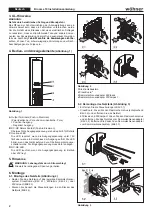
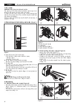
7. Connection
(Figure 4)
Figure 4
A
Output Terminals (push-in terminals)
(Two ide poles and two identical - poles)
+ Positive output
– Negative (return) output
B
DC-OK Relaiy Contact (push-in terminals)
Monitors the output voltage, see chapter 8 for details.
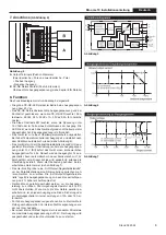
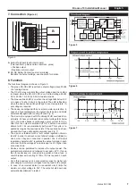
8. Function
The functional diagram is shown in Figure 5.
• The green DC-OK LED reports an output voltage above 20Vdc
of a running device.
• The DC-OK relay monitors the output voltage and the contact
is closed, when the DC- OK LED is on. Contact ratings: 60Vdc
0.3 A, 30 Vdc 1 A, 30 Vac 0.5 A for resistive loads.
• The blue overload LED is on, when the voltage falls below 19 V
or in case of a short circuit in the output. The LED is flashing,
when the device has switched off due to over-temperature. In
-
put voltage is required.
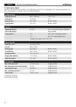
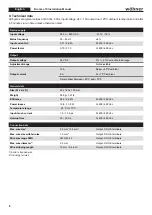
• The device is equipped with an over-temperature protection. In
case of a high temperature, the output shuts down and starts
automatically again after cooling off (see Fig. 6).
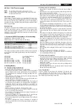
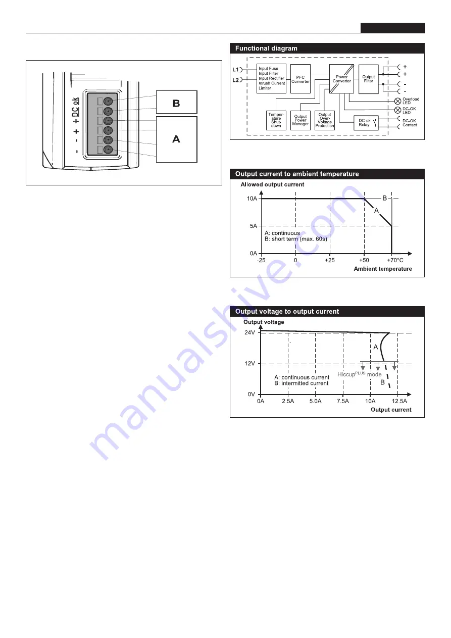
• The device is equipped with the HiccupPLUS overload char
-
acteristic. At heavy overloads (when output voltage falls below
13 V), the device delivers continuous output current for 2.8 s.
After this, the output is switched off for 7s before a new start
attempt with 1.2 s is automatically performed. This cycle is re
-
peated as long as the overload exists. If the overload has been
cleared, the device will operate normally (see Fig. 7)
• The device is featured with a “soft output regulation charac
-
teristic” in order to achieve current share between multiple de
-
vices, when they are connected in parallel. The “soft output
regulation characteristic” regulates the output voltage in such
a manner that the voltage at no load is approx. 4% higher than
at nominal load.
• Devices can be paralleled to increase the output power. The
ambient temperature is not allowed to 45°C. If more
than three devices are connected in parallel, a diode, fuse or
circuit breaker with a rating of 15 A or 16 A is required on each
output.
• Up to three devices can be connected in series for higher out
-
put voltages. Avoid return voltages from the load to the output.
• In case of an internal defect, a redundant circuit limits the
maximum output voltage to 32 V. The output shuts down and
automatically attempts to restart.
Figure 5
Figure 6
Figure 7


