WOERNER 612345/1 Translation Of The Original Operation Manual Download Page 14


Operation manual GMK-A 

Page 14 of 35 

B0887 

4.  Functional description 


4.1  Drive 

 
The unit is driven by a DC motor, which is laterally screwed on the pump casing. The motor 
is energised by externally switching the voltage supply. For that purpose, an external con-
troller is required. 
 

4.2  Operation 


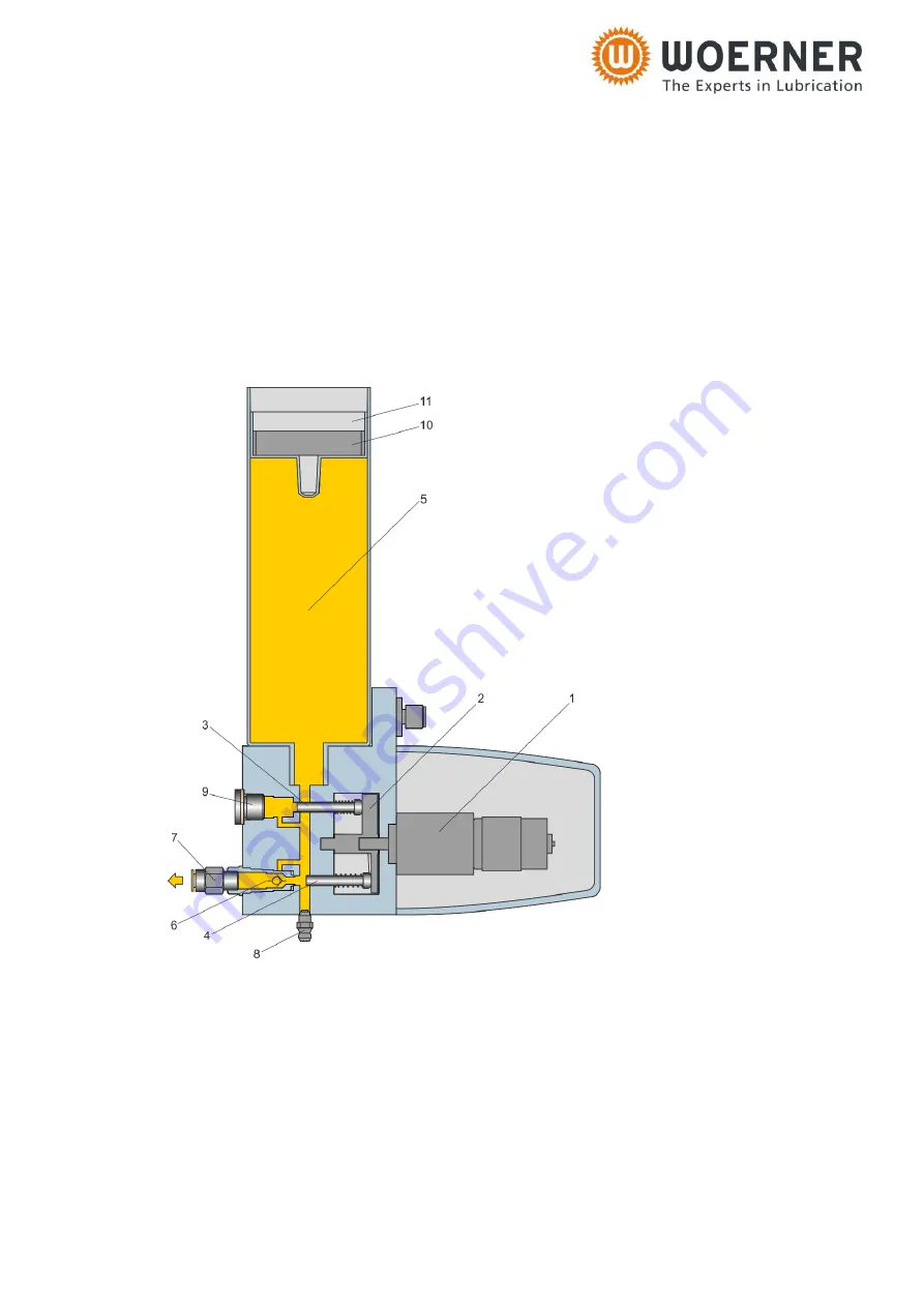
The rotational movement of an electric motor 

1

 is converted via a swash plate 

2

 into a lifting 

movement of the delivery pistons 

3

 and 

4

. In the suction position (piston 

4

) the medium is 

drawn in from the reservoir 

5

, in the pressure position (piston 

3

) the medium is pumped to-

wards the outlet. 
At flow the medium flows through the integrated non-return valve 

6

 to the outlet. Lubricant 

lines can be connected with the optional push-in fitting 

7

. An empty reservoir 

5

 can be refilled 

via the grease nipple 

8

Summary of Contents for 612345/1

Page 1: ...Operation manual GMK A Page 1 of 35 B0887 Piston pump GMK A Translation of the original operation manual Version EN 05 2019...

Page 2: ...tency in the translated text occurs the original German operation manual should be referred to for clarifi cation or the manufacturer contacted Copyright Unless permitted explicitly the dissemination...

Page 3: ...9 3 5 Technical data 9 3 5 1 Assemblies 9 3 5 2 Dimensions 10 3 5 3 Technical data 12 4 Functional description 14 4 1 Drive 14 4 2 Operation 14 4 3 Functional check 15 4 4 Level control 15 5 Safety no...

Page 4: ...ault remedy and repair 30 8 1 Cleaning 30 8 2 Servicing 30 8 3 Inspection schedule 31 8 4 Repair 31 8 5 Accessories 31 9 Return shipment to factory 32 10 Disposal 34 11 Appendix 34 11 1 Content of the...

Page 5: ...are obliged to read and understand this opera tion manual and in particular its section Safety regulations It is your safety that is at stake Should you have any question or uncertainty contact WOERNE...

Page 6: ...f causing serious personal injuries Warning Any possibly dangerous situation capable of causing serious personal injuries Caution Any possibly dangerous situation that might cause minor per sonal inju...

Page 7: ...de of the pump body and contains information as follows Manufacturer Type e g GMK A No order number e g 612345 1 Model year 2 4 Manufacturer and contact address Eugen Woerner GmbH Co KG Hafenstrasse 2...

Page 8: ...ange other than that described above The lifetime is 50 000 strokes regardless of the number of outlets used Depending on the version these limits of use may be restricted further Such further restric...

Page 9: ...l atmospheric pressure 1013 mbar by more than 0 5 bar as well as that of highly inflammable or explosive media and foodstuff is prohibited Important Please also note the safety data sheets pertaining...

Page 10: ...Operation manual GMK A Page 10 of 35 B0887 3 5 2 Dimensions Weight with reservoir 380 250 125 approx 1 8 kg with reservoir 40 approx 3 5 kg with reservoir 04 05 approx 3 0 kg see also data sheet P0887...

Page 11: ...Operation manual GMK A Page 11 of 35 B0887...

Page 12: ...Motor Voltage 24 VDC Current consumption max 0 5 A Level control for reservoir 380 250 125 Voltage 10 30 VUC Switching current max 0 25 A Switching capacity 5 W VA Switching function NC contact at mi...

Page 13: ...29 IP67 Switching function NC contact at min Connection diagram Reservoir 04 Equipment for cartridges 400 g System Lube Shuttle Reservoir 05 Equipment for cartridges 500 g System Reiner the following...

Page 14: ...rotational movement of an electric motor 1 is converted via a swash plate 2 into a lifting movement of the delivery pistons 3 and 4 In the suction position piston 4 the medium is drawn in from the res...

Page 15: ...ontrol A magnetic tape 10 in the follower piston 11 of the reservoir 5 dampens an integrated reed contact when the reservoir is empty The signal is emitted as long as the magnetic tape is within the d...

Page 16: ...ent use of the unit 5 2 Requirements on user training Any person getting to work on the unit must be authorised and trained for that purpose by the operator They must be able to recognise and avoid po...

Page 17: ...property damage As experience shows possible incorrect applications include for instance the following the delivery of highly inflammable or explosive media the delivery of media being capable of reac...

Page 18: ...han original spare parts may be used The operator is required to regularly check and maintain all pro tection safety and monitoring facilities After every repair the flawless condition of the unit mus...

Page 19: ...It is to be secured by means of two M5 screws at the both female threads of the pump body The device is screwed from the rear side For this purpose through holes are required on the wall surface The m...

Page 20: ...an also use this signal for an emergency shutdown in case one or more lubricant lines are blocked WOERNER recommends programming the external control as follows If with the unit switched on no new sig...

Page 21: ...for sealing the reservoir is completely in the countersink If necessary insert the O ring separately be fore screwing in the cartridge 6 5 1 2 Assembly of the reservoir type 40 Mounting the reservoir...

Page 22: ...plied Make sure that the O ring for sealing the reservoir is located in the sinking 6 5 1 4 Closing an outlet 1 Remove any existing lubricant lines 2 Unscrew the non return valve cartridge using an op...

Page 23: ...plug with sealing ring 6 5 1 5 Restoring an outlet that has already been closed 1 Unscrew the screw plug remove the sealing ring 2 Check the completeness of the non return valve cartridge before screw...

Page 24: ...manual GMK A Page 24 of 35 B0887 3 Screw in the non return valve cartridge Tighten to 30 Nm Note The collar on the SW12 hexagon does not necessarily have to be in contact with the countersink in the...

Page 25: ...Operation manual GMK A Page 25 of 35 B0887 4 Screw in push in fitting 5 Connect lubricant lines...

Page 26: ...cal grease nipple to sealing nipple 1 Unscrew the conical grease nipple on the hexagonal head 2 Screw in sealing nipple 6 5 1 7 Conversion from conical grease nipple to locking coupling 1 Unscrew the...

Page 27: ...y when the upper edge of the following piston is about 10 mm away from the upper edge of the cartridge reservoir The venting process may be shortened if the filling is performed while the unit is runn...

Page 28: ...unit Switch on and off the unit that many times until the lubricant emerges free of air from the lines This operation can be short ened by ascending the tubes towards the outlet 6 6 Shutdown The unit...

Page 29: ...ctric connection to the monitoring device 3 No response from Monitoring function Unit overloaded Switch off the unit by disconnecting the power supply and check the lines from the unit to the lubricat...

Page 30: ...e with DIN VDE 1000 10 8 1 Cleaning Important The unit must not be cleaned by means of high pressure clean ers or compressed air Important The use of solvent containing cleaning agents may incur dam a...

Page 31: ...in fitting 4 943 600 61 Polyamide tubes or hoses with connectors with claw groove Straight push in fitting 6 943 600 48 Polyamide tubes or hoses with connectors with claw groove Locking coupling G1 8a...

Page 32: ...e original must be attached to the freight documents For damage assessment and in order to be able to perform the repair quickly and eco nomically we furthermore need a detailed description of the com...

Page 33: ...harged and cleaned 2 the residual contaminations left are free of any substance being harmful to health or environment 3 the materials used by us in the product s comply with the notes on the purpose...

Page 34: ...e declaration of conformity We hereby declare that the products GMK A as of model year 2018 meets all relevant provisions of the directive on machinery 2006 42 EC Furthermore the machine complies with...

Page 35: ...Operation manual GMK A Page 35 of 35 B0887 11 2 Declaration of conformity...

Reviews: