background image

22
22

8.4 System setting

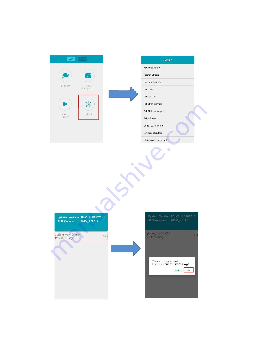
Press the “Setting” button to enter the configuration menu as follows.

Figure 29

1. Upgrade the software of driver fatigue monitoring system

To upgrade the software, first save the update pack to the

Micro SD

card, and then insert the card

into the device and powers up the device. After connecting App to the device through Wi-Fi, select

“Upgrade System” item to choose the update pack, then the system will update automatically. After

appearing the “update success” message, reboot the driver fatigue monitoring system to start the

updated system.

Figure 30

Summary of Contents for MRF500A

Page 1: ...Operating Instructions Driver Monitoring System DMS Face Login Recognizer MRF500A Please read this manual thoroughly before operating the device and keep it for future reference V1 0...

Page 2: ...n of the driver fatigue monitoring system 7 5 2 System connection and Cable definition 7 6 Installation Calibration 9 7 DMM and FRS functions 13 7 1 Driver Monitoring Module DMM 13 7 2 Face Recognitio...

Page 3: ...uate air circulation around the device 9 The device is not designed to be waterproof Operating Precautions 1 The device may be powered by a 12 24 volt automotive battery or vehicle electrical system P...

Page 4: ...thinner as they might damage the finish of the device Caution Risk of electric shock Do not open Caution to reduce the risk of electric shock Do not remove cover or back No user serviceable parts insi...

Page 5: ...red to the system Recognize the driver in 5 second return the result by voice Record real time video about the driver who cannot be recognized successfully 3 DVR 1280 720 25f or 30f H 264 HD video Max...

Page 6: ...2W Coding ADPCM Storage Type Capacity Micro SD card Max 256G Format AVI Sensor G sensor Built in GPS Built in Wireless Wi Fi 802 11b g n 150Mbps Power Input DC 10 36V Consumption Max 4W Temperature Op...

Page 7: ...cription 1 driver fatigue monitoring system 1 Extra power wire 4 Pin aviation male connector to DC female connector 1 Relay Kit for Imobilizer 1 Optional Monitor Supports analog video input Diagram 2...

Page 8: ...tion and Cable definition The system connection based on driver fatigue monitoring system is as follows The device Wi Fi hot spot is point to point just for calibrating and setting the device paramete...

Page 9: ...he Cable 2 4PIN Aviation male DC Female Connector Figure 5 Definition of the 4 PIN aviation male connector Definition of the DC female connector Figure 6 The left end of Cable 1 is connecting to insid...

Page 10: ...evice setting etc Figure 7 1 Building the Wi Fi connection Before calibrating the driver fatigue monitoring system or setting the parameters of the device make sure the device is powered on Then refer...

Page 11: ...10 Figure 8 3 If it is first time to connect the Wi Fi hot spot It may prompt the massage as follows choose the connect button to remain the valid connection Figure 9...

Page 12: ...bout 7m please keep in this range Figure 10 After finishing Wi Fi connection we can calibrate the driver fatigue monitoring system or operate some other settings about the device according to the APP...

Page 13: ...and the front view of the driver is greater than 10 degrees the assistant should rotate the device on the dashboard slightly until the square turn and stay green 2 After making sure the color square...

Page 14: ...pter 8 4 for the operation guidance When a warning is triggered the device will send out a voice to alarm the driver record the video of this warning event and the warming information can transfer to...

Page 15: ...ts that the driver turns his her head to one side left or right more than about 30 degrees for a long time about 5 seconds Figure 22 3 Driver Calling Warning Driver calling warning is triggered when t...

Page 16: ...ng is triggered when the device detects that the driver keep smoking for a time more than about 3 seconds Figure 24 5 No driver warning No driver warning is triggered when the device cannot detect a d...

Page 17: ...confirming it comes to a live video screen with an assisting square Make sure that the driver s face is fully in this square For better face recognition it s strongly recommended that the driver shake...

Page 18: ...l pop up a notice to select whether to register another new driver new face or to finish the registration It may take some time from a few second to 2 minutes to finish the registration according to t...

Page 19: ...l prompt a message when the APP is reconnected To choose the CANCEL button to abandon the last registration or to choose the REGISTRATION button to finish last registration Figure 16 2 Manage the driv...

Page 20: ...ce The recognition results are feedback both by voice and notice in the video of monitor as follows Once Face recognize match and got success it can be configured for immobilizer to triger an output t...

Page 21: ...20 20 8 Functions of the APP 8 1 Calibration Refer to Charter 6 8 2 Face Recognition Refer to Charter 7 1 Face Recognition Figure 26...

Page 22: ...e is ABNORMA DRIVING page for the video of DMM warning events another is FACE RECOGNITION page for the video of FRS failure events which may indicate an illegal driver Figure 27 Short press on one of...

Page 23: ...e first save the update pack to the Micro SD card and then insert the card into the device and powers up the device After connecting App to the device through Wi Fi select Upgrade System item to choos...

Page 24: ...ng and this process may take about 1 minute in a good signal environment 3 Other settings Setting Setting description Restore factory All setting parameters are restored to the default value Format SD...

Page 25: ...rily mean a failure within the display Please check the following items before you initiate request for repair Symptoms Possible Causes Solutions No picture no sound Improper connection of automobile...

Page 26: ...25 25 WISTRON Intelligent www wnc com tw E mail info wnc com tw...

Reviews: