


867-205
P2007 Jens Broecking © Firma WJG, Braunschweig. Nachdruck oder Vervielfältigung nur mit ausdrücklicher Genehmigung
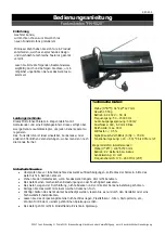
1. Battery Compartment
2.
BATT: Battery indicator LED. Lights up when the device is switched on and the battery are strong
enough. If the battery is weak the light goes out.
3.
ON/MUTE/OFF: On-position / muting / off-position. The device still consumes energy when set to MUTE!
4.
Mikrophone connector.
5.
CH1/CH2: Toggle for using channel 1 or channel 2 for sending.
6.
LED: Over-modulation indicator.
7.
MIC-ADJ: Rotary switch to adjust the input sensitivity. A sensitivity which is to high results in over-
modulation while a sensitivity which is to low results in a noisy signal.
The Receiver and its Functions:
1.
POWER: On-/ Off-Switch.
2.
CH.A SIGNAL: Signal indicator of channel A (LED).
3.
CH.B SIGNAL: Signal indicator of channel B (LED).
4.
CH.A OUT LEVEL: Volume control of channel A.
5.
CH.B OUT LEVEL: Volume control of channel B.
6.
ANT B: Antenna for channel B.
7.
AF OUTPUT BALANCED B: Balanced output of channel B.
8.
AF OUTPUT BALANCED A: Balanced output of channel A.
9.
UNBALANCED: Unbalanced output for mixed channel A/B.
10.
Connector for power supply cable.
11.
POWER: On-/ Off-Switch.
12.
ANT A: Antenna for channel A.


