Gearless Lift Machine
WSG-W8
Operating Instructions
Seite/page
22
Datum/date
29.01.2010
Stand/version
0.13
Änderungen vorbehalten!
Subject to changes without notice!
In the very rare case of load compensation between the
car and the counterweight, the electric return motion
control must be used.
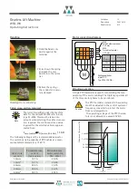
When required and if expressly ordered, the attachable
manual turning device No. 504 090 (35) can be supplied.
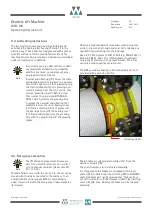
This completely assembled device is composed of a worm
wheel (36) with two stationary plug-in bolts (37), a worm
gear shaft (38) with a hand wheel (39), the bearing block
with the stop plate (40), the centre bolt (41) and two fas-
tening bolts (42). The centre and fastening bolts are cap-
tivated with nuts which must be removed when the
device is to be used.
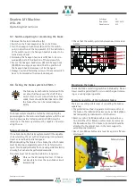
The manual turning device is available in three versions:
Use of the manual turning device is the sole responsibili-
ty of the user. All W7/W8 lift machines with delivery
dates on or after 10/2005 are designed for attachment of
this complete device.
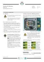
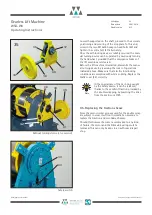
If such a manual turning device is provided, the lift
machine is equipped with the safety switch (43) shown
opposite, which must be incorporated into the safety cir-
cuit of the lift system.
Operating data of the safety switch:
During normal operation the safety contact remains
closed by virtue of a bow on the switch cover. Before
using the manual turning device in an emergency, this
cover (34) (4xM6 wing nuts) must first be removed. The
two pinholes - 15 in dia. and 60 mm apart - in the shaft
of the lift machine will then be visible. Turn the hand
wheel (39) of the manual turning device so that the posi-
tion of the plug-in bolts (37) approximately matches that
of the pinholes. Remove nuts from the bolts 41 and 42
(captivation), then lift the device onto the lift machine in
a position where the two plug-in bolts (37) slip into the
pinholes in the shaft and the stop plate (40) of the
device is brought up axially to the bearing battens (44)
of the frame. Then screw the centre bolt (41) loosely into
the tapped hole in the shaft. With the turning device
Item no
.
version with view of the traction sheave weight
504 090 001
left
hand wheel left
23 kg
504 090 002
right
hand wheel right
23 kg
504 090 003
uni
long shaft; hand wheel left
and right intermateable
25 kg
Type:
AZ 14-1 (Schmersal)
Utilisation category
AC-15, DC-13
I
e
/ U
e
2 A / 230 VAC
2 A / 200 VDC
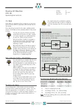
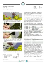
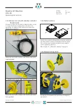
Installation of the manual brake releasing device
1. Insert all Bowden cables into the lever block, making
sure that the nut (1) is screwed flush onto the stud
bolt (2).
2. Insert the ends of the Bowden cables into the
machine.
3. Then insert the sleeve ends. A certain amount of effort
is needed, as the cables require some preloading.
Note
:
The Bowden cables should be kept straight and not
wound.
4. Preload the Bowden cables by turning the nuts on the
stud bolts (2). The brakes must not yet release (
check
this!
).
5. Fit the manual releasing
lever and check that the
brakes are properly
released.
2
1


