background image

MTH400  User Manual


12


10 different configurations are available: 


FACTORY configuration is a locked configuration: no parameter can be changed. 


USER  configuration  is  the  only  configuration  that  can  be  saved  using  the  OLED  display  (see 
<PRESET>  menu). Note: It is not possible to change the name of this configuration. 


Other  8  configurations  where  the  user  can  change  both  the  name  and  the  values  of  all 
parameters.  

INTERFACE AND DEVICE PANEL (

At  the  beginning,  the  program  checks  which  IR  devices  are  detected  and  they  appears  on  the 

Interface

 panel. 

The user has to select the device and push <connect> button in order to open the communication 
with the IR device. A picture on the top in the Interface panel help the user in this selection showing 
the  type  of  devices  detected.  During  this  process  the  “IR  activity”  led  blinks  to  indicate  that  the 
program wait connection’s answer from the IR device.  

A  successful  connection  is  signaled  with  the  “interface  connection”  green  led,  while  a  failed 
connection is signaled with the “communication error” led. 

Once  a  supported  device  is  found,  the  software  automatically  reads  all  the  data  related  to  the 
remote configuration, as well as the frequencies that are pre-programmed.  

Firstly, in order to avoid unwanted operation, no parameters can be changes and the EDIT button, 
presents  on  the  bottom  of 

Device

  panel,  is  yellow  and  set  to  LOCKED  state.    Pushing  the  EDIT 

button,  it  becomes  grey  and  sets  to  UNLOCKED  state  to  indicate  that  the  configurations  can  be 
modified. 

In  this  panel  it’s  possible  to  assign  a  name  to  the  TX  (not  available  for  FW  v.1.22.0F  or  previous). 
Under this parameter, there is a flag to hide the info menu on the TX (not available for FW v.1.22.0F 
or previous) 

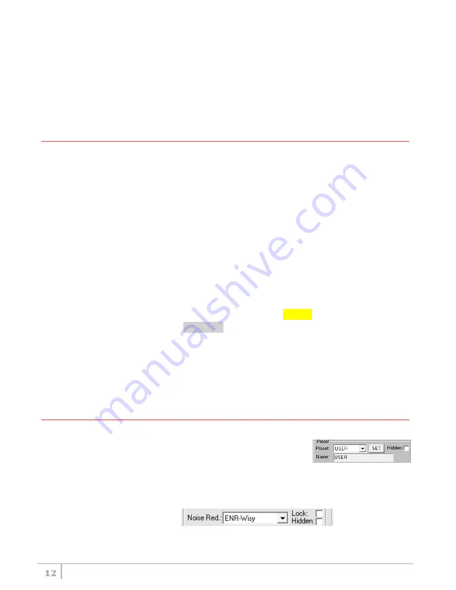
CURRENT SETTINGS PANEL (

In the Current Settings panel the user can 


with Preset panel → load one of the 10 available configurations 


with  other  panels  →  modify  all  the  configuration’s  parameters  (the  same  that  are 
changeable  in  the  OLED  display).  Each  parameter  can  be  locked  or  hidden  clicking  the 
related lock/hidden button, so the set value cannot be changed next or cannot be visible on 
the OLED display.  

ATTENTION:  All  the  modifies  applied  to  the  Current  Settings  panel  are  instantaneous:  they  are 

Summary of Contents for MTH400

Page 1: ...MTH400 User Manual Wideband Wireless Professional Handheld Transmitter SN ________________ Rev 06 rif FW 1 30 0A Date 13 May 2015...

Page 2: ...MTH400 User Manual 2...

Page 3: ...n the back the Batteries holder Infrared area fig 2 MIC Antenna made with fibreglass reinforced housing and with a Wireless power switch fig 3 MIC Antenna is fastened to body with 2 anvils and a micro...

Page 4: ...ed use only replacement parts authorized from the manufacturer Substitution with not authorized parts could result in electric shock hazards or fire Keep attention on all the labels with warnings or h...

Page 5: ...D B Channel selection buttons ch C MIC gain setup buttons gain D 3 position selector up down click Fig 4 OLED POWER UP OLED IS IN OFF CONDITION Pushing down selector click the graphic display oled tur...

Page 6: ...00 640 000 2 566 000 798 000 3 510 000 698 000 AUDIO AF In Gain AF Level 40 40 dB 1dB step 54 26 dBu 1dBu step Phase 0 180 HP Filt Flat or 60 80 120 170 250 400 Hz Noise R ENR Wisy ENC Wisy RF Battery...

Page 7: ...there is RF10 RF 50 or RF 100 the transmission is active respectively at 10 50 or 100mW see RF BATTERY menu On left side the battery bar is displayed PRESET menu This menu can be entered by scrolling...

Page 8: ...udio peak 0 dB nominal deviation 40KHz Set the gain with the maximum input signal avoiding the peak on the audio bar TRY TO SETUP TO HAVE A MAX PEAK HOLD BAR CLOSE TO 6dB Using quick gain setup button...

Page 9: ...r It s possible to enter on this menu also pressing at the same time the CH GAIN buttons B C INFO menu This menu can be entered by scrolling selector In this menu it s possible to see FW version HW ve...

Page 10: ...duction ENR Wisycom Extended NR noise optimized ENC Wisycom Extended NC voice optimized RF BATTERY RF Power RF Power 10mW or 50mW or 100mW depending on the power profile Battery Battery type Alkaline...

Page 11: ...OTE Wisycom IR Programmer doesn t work whit MRK950 MRK960 if it is connected to the PC using an Ethernet cable The Wisycom IR Programmer s window is divided in 4 parts see the image below Interface an...

Page 12: ...naled with the communication error led Once a supported device is found the software automatically reads all the data related to the remote configuration as well as the frequencies that are pre progra...

Page 13: ...oup lock hidden group To change a frequency value for a specific channel double click on the grid frequency panel row channel s number insert the new frequency value and press OK button To lock hide a...

Page 14: ...ng the LOAD SAVE button at the bottom of the panel it is possible to load save the frequencies for the selected group from to a wdf file To save the frequencies of all the groups click to the related...

Page 15: ...action NOTE a trick In case of the user have a locked parameter and he is in great need for modify it he can save the configuration to USER configuration by OLED see PRESET menu and then load the USE...

Page 16: ...0 dB SPL 0 5 THD with MCM301 MCM302 MCM303 MCM304 MCM305 condenser heads Noise Reduction ENR Wisycom Extended NR with independent Attack and Recovery time noise optimized ENC Wisycom Extended NC with...

Page 17: ...ada JP max power 10mW limited to 714MHz Japan NZ max power 100mW limited to the range 502 698MHz New Zealand VARIANTS COLOR PV body color titanium gray ceramic coating BL body color black powder coati...

Page 18: ...MHz 10mW Japan MTH400 NZ EN 300 422 1 2 EN 300 454 1 2 Limited to the range 502 698MHz 100mW New Zealand MTH400 0W1 MTH400 EUX is not an SRD device it requires specific authorization by your local fre...

Page 19: ...waste or return them to your specialist dealer In order to protect the environment only dispose of exhausted batteries FCC Conformity This device complies with Part 74 of the FCC Rules Operation is su...

Page 20: ...el cassonetto barrato riportato sull apparecchiatura o sulla sua confezione indica che il prodotto alla fine della propria vita utile deve essere raccolto separatamente dagli altri rifiuti La raccolta...

Page 21: ...MTH400 User Manual 21 DECLARATION OF CONFORMITY...

Page 22: ...MTH400 User Manual 22...

Page 23: ...MTH400 User Manual 23...

Page 24: ...MTH400 User Manual 24 Wireless System Communications Via Spin 156 I 36060 Romano d Ezzelino Italy Tel 39 0424 382605 Fax 39 0424 382733 www wisycom com e mail sales wisycom com...

Reviews: