Pag. 15
high performances microphone system
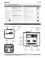
Analogue Audio XLR
Analogue
Digital
Digital
Digital Audio AES/EBU
Digital Audio Ethersound
Link Ethernet 10/100 Base-TX
Link USB
RECEIVER CONNECTION
Antenna Connection
The MRK950 has two antenna inputs, necessary for
a true diversity reception system. Each input sig
-
nal is splitted for the two diversity receivers on the
MRK950. The picture on the bottom of the page
shows the typical connection of four MRK950 re-
ceivers. Each antenna input could deliver a booster
supply of 200mA at 12Vdc; this is enough to sup
-
ply an active antenna like the
Wisycom LBNA
and
a booster like the Wisycom BAA, needed only when
the antenna cable has a very high attenuation. For
connecting more receivers on same antennas, use
active wideband antenna splitters like the Wisycom
SPL214AW for four MRK950 (8 wireless microphone
channels) or the SPL218AW for eight MRK950 (16
wireless microphone channels). More channels are
possible combining more splitters. In this case the
active antennas and the boosters will be powered
by the splitters. Using the MRK950EX version it is
also possibible to use the integrated active splitter to
connect several MRK950EX in cascade configuration.
Analog audio connection
The MRK950, in the full optional audio output con-
figuration, has three audio outputs for each receiver,
two balanced with XLR connector and one unbal
-
anced with a 1/4” (6.3 mm) stereo jack connector.
The unbalanced audio output has the same audio
signal of the LINE output. The balanced audio out
-
puts could be electronically balanced or transformer
isolated with very low impedance when the
TRafo
option
is installed.
Below the XLR connectors there are two switches:
The left one (LINE/MIC) inserts a fixed resistive at
-
tenuator of 30dB on the audio output; the audio lev-
els on the XLR connector, according to the setting of
the “
out level
” and to the setting of the switch be-
low the XLR connectors, at nominal modulation, are:
Out lev 12dBu Out lev 6 dBu
Out lev 0 dBu
Att. 0dB
12 dBu
6 dBu
0 dBu
Att.30dB
-18 dBu -24 dBu -30 dBu
The switch on the right (LIFT/) cuts the connection
beetween the pin one of the XLR connector and the
ground of the MRK950 to avoid ground loops.
Digital audio AES/EBU
With the AES/EBU option installed the MRK950 has
an digital audio output channel according to the
AES3 and AES/EBU standards for professional 24 bit
digital audio.
The left channel of the AES3 stream is the audio of
the receiver 1 and the right channel is the audio of
the receiver 2. When no word clock is connected,
the sampling rate of the digital audio output is fixed
at 48KHz, internally crystal generated; with the ex-
ternal word clock the sampling rate could be from
32KHz to 108KHz. The word clock input could be left
at high impedance or loaded to 75 ohms. The word
clock output could be connected to the next MRK950
or could be left open.