background image

Pag. 11

high performances microphone system

tors always, it could be muted only by the squelch 

on  RF  signal  (the  RF  squelch  has  always  priority). 

Tone squelch ON enables the audio output on LINE 

and COM (if present) only if the transmitter sends 

the correct identification tone signal (tone squelch). 

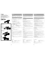
The ADV function (with or without  PTT options), on 

microphone transmitters, gives more possibilities of 

audio routing and GPI signalling. In the picture be

-

low is displayed the matrix menu. To have access to 

this menu is needed to set the tone squelch function 

in ADV and then press the upper button “CONFIG”:

With  the  knob  and  the  buttons,  it  is  possible  to 

choose,  for  any  one  of  the  three  TSQ  modes,  the 

status of the audio outputs LINE and COM and in the 

TSQ  ADV  mode  it  is  possible  to  choose  the  status 

of outputs LINE, COM and GPI, when the transmit

-

ter PTT button is released or pushed. The dot in the 

circle on the left of the display shows the actual set-

ting for the tone squelch function.

Note: the tone squelch could not substitute 

the squelch on the RF signal level. For the 

best performance of the receiver it is bet-

ter to use the SQUELCH & TONE SQUELCH 

together.

Out level

The 

oUT leVel

 function allows the adjustment of 

the audio level on the LINE and COM balanced out

-

puts. The nominal level, used also in the technical 

specifications  of  the  receiver,  is  12dBu  at  nominal 

modulation and could reach 18dBu to 20dBu in clip

-

ping.  This  level  could  be  too  high  for  some  audio 

mixing units, so with the out level function it is pos-

sible to reduce the nominal level from 12dBu to 6dBu 

or 0dBu. This setting is unique for LINE and COM and 

for all the two receivers. 

Note: the audio output level could be further 

reduced by 30dB with a switch below the XLR 

output connector, in the rear panel.

Cal. tone

The 

caliBRaTion  Tone

  function  generates  an 

1KHz  sine  audio  tone  at  the  audio  outputs  at  the 

nominal level on the selected receiver.

Before starting the tone it is possible to select with 

the knob the outputs for the tone (only LINE, only 

COM or LINE and COM together). With the buttons 

it  is  possible  to  start,  stop  and  exit  from  the  tone 

generation. The calibration tone is generated by an 

analog source when the noise reduction system se-

lected is analog.  The calibration tone is a very low 

distorsion  digital  generated  when  the  noise  reduc-

tion system selected is digital (from DSP board). 

The output not selected for the tone generation will 

be muted.

When the tone is active at least in one output, the 

led bar of the deviation indicates the 100%, just to 

remember that the tone has the same level of the 

nominal deviation in a transmitter.

Sync

The 

sYnc

  function,  selected  from  the  main  menu 

with the lower button, is useful to tune a transmit-

ter on the same frequency of the receiver via the IR 

interface. Before starting the sync function tune   the 

receiver on desired channel, manually or using the 

SCAN  utility.  After  this,  enable  the  IR  interface  on 

the transmitter. Now press the knob and the lower 

button to start the SYNC function. Keep the IR win

-

dow of the transmitter in front of the IR window of 

the receiver and, as soon as the connection is done, 

the receiver will send to the transmitter all the in-

formation needed. If the operation is not possible, 

(i.e.  the  frequency  range  of  the  transmitter  is  not 

compatible with the frequency of the receiver), the 

display will show an error message. If the transmit

-

ter has the function “NAME” enabled, when the sync 

function is completed it will show the same name of 

the syncronized receiver.

SQ (squelch autoset)

The 

sQUelcH aUToseT

 function helps the user to 

set the squelch level of the receiver at a good level 

for the selected channel. After pressing the SQ au

-

toset button, the two receivers ask to switch off the 

transmitter and then, after the user confirmation (on 

one  receiver  or  all  the  two  receivers  at  the  same 

time), it starts to measure the noise in the selected 

channel.


A few time later, after some calculation, the receiver 

Summary of Contents for MRK 950 EX

Page 1: ...INSTRUCTION MANUAL DUAL HIGH PERFORMANCE WIRELESS MICROPHONE RECEIVER FULL UHF BAND COVERAGE UP TO 370 MHZ MRK950 s n _______________ FW rel _______________ Options _______________...

Page 2: ...Pag 2 MRK950 dual true diversity receiver...

Page 3: ...in card pc like thru the DEXB expansion bus Moreover MRK 950 system is already set up for the exclusive PTT function remote command devel oped and patented by Wisycom and now appreciated in the broad...

Page 4: ...es or replacement parts autho rized or specified from the manufacturer Do not supply more than 7 apparatus MRK950 from the mains output see power requirements for other apparatus Clean the apparatus o...

Page 5: ...gnals from section A B to have the best audio The demodulated signal is then splitted on two parts one part flows to the analog processor and the other part flows to the digital audio processor option...

Page 6: ...nt operation replicates all the analog functions with very high ac curacy ultra low distortion and without typical an alog problems like components tolerances or long term drifts or temperature drifts...

Page 7: ...be off then push SQ button to let the system find the optimal value You can later accept modify or discharge this setup IR interface window for communications between the MRK950 and a transmitter You...

Page 8: ...tter battery charge status Thru the main menu on the LCD display and the LED bars for the RF level and modulation the user has the complete monitoring in real time of the wireless channel in use Menu...

Page 9: ...group of channel This short name 8 char acter is displayed at the right of the group number in the main display view First chose the the group and then press the knob You will be able to edit any char...

Page 10: ...o menu The second item on the menu tree is AUDIO Pressing AUDIO middle button you enter the AU DIO functions menu as shown here below AUDIO Noise red Tone sq Out level Cal tone Noise red The NOISE RED...

Page 11: ...nominal level on the selected receiver Before starting the tone it is possible to select with the knob the outputs for the tone only LINE only COM or LINE and COM together With the buttons it is possi...

Page 12: ...in rank order to find the less noisy channels because they are in the left part of the graph The marker is always active rotating the knob Pressing the knob the graph changes between rank order to ch...

Page 13: ...ble in respect to the dy namic range of the audio signal and the manufac turer specifications If the receiver MRK950 has the DSP board option the scale of the modulation will be changed according to t...

Page 14: ...11 GPI output of the receiver 2 1 4 6 3mm ste reo jack socket Optional 12 XLR 3 pin male connector COM audio output of the receiver 1 balanced Optional 13 XLR 3 pin male connector LINE audio output o...

Page 15: ...r two balanced with XLR connector and one unbal anced with a 1 4 6 3 mm stereo jack connector The unbalanced audio output has the same audio signal of the LINE output The balanced audio out puts could...

Page 16: ...USB A to USB B cable to build a chain of receivers The maximum number of receivers in a chain is four The receiver with the USB connector free is the subnet controller receiver the one in the upper p...

Page 17: ...e squelch it works by decoding the special key sub car rier digitally modulated present on the carrier of the ac tual Wisycom transmitters The tone squelch function can be inhibited for compatibility...

Page 18: ...al audio distribution on a single cat 5 Ethernet compatible cable Needs DSP audio board installed Two RJ45 connectors for input and output data lines Obblighi di informazione agli utilizzatori Modello...

Page 19: ...Pag 19 high performances microphone system...

Page 20: ...no d Ezzelino Italy Tel 39 0424 382605 Fax 39 0424 382733 www wisycom com e mail sales wisycom com WISYCOM srl reserves the right to make changes at any time and without prior notice Printed in Italy...

Reviews: