background image

8

Explore Screen Configuration

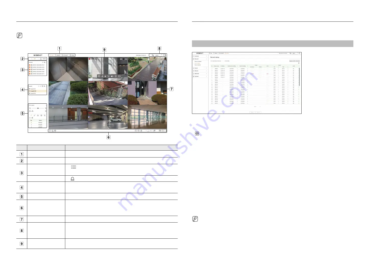
The recorder screen consists of the following.

■ 

The screen may be configured differently depending on the menu selected by the user.

No.

Screen configuration

Detailed description of function

Menu

Clicking on each menu takes you to the corresponding menu screen.

List/Event

Select to view list of cameras or events.

Camera List

Click 


List

 to display list of registered cameras in the recorder.

You can also register the camera manually or automatically.

Event List

Click   

Event

 to display list of events.

Layout List

This displays a list of the default layouts and the layouts that have been created.
You can set and play sequence on the list of layouts.

PTZ Control

Controls the connected PTZ camera.

Function Buttons

Function that is frequently or urgently used.
(export, alarm stop, manual recording, OSD display, channel information, check camera status, auto-switch screen, 
split mode setting, change aspect ratio, switch to full screen mode)

Video Window

Shows the video of the camera connected to the recorder.

Display System Status and 
Additional Functions

● 

Displays the status of the system, hard disk, and network.

● 

The ID of the connected user is displayed.

● 

Displays a QR code to download User Manual.

Display Events and 
Functions to Control Videos

Displays events that occurred on the camera and functions related to video control.

Record Setup

You can set resolution, IPS, and quality of recordings by channel, and by recording type of standard / event.  
You can check frame rates and data transfer amount of Full Frame and Key Frame recordings for each channel, and 
set the transfer limit for recordings.

Setup > Record > Record setup

● 

Apply to other channels : If you select <

Apply to other channels

>, “

Apply to other channels

” confirmation 

window will appear. After selecting channels that the settings will be applied to, click on <

OK

> to apply them to 

the selected channels. 

● 

 : The camera of the corresponding channel is displayed on the list or as a thumbnail. 

● 

Camera name : Displays the camera name.

● 

IP Address : Displays the camera IP address. 

● 

Continuous recording / Event recording : Set the recording method for Continuous recording or Event recording.
–  Full frame : Records all frames fed by the camera.
–  I-frame : Records only key frames fed by the camera. Depends on camera settings.
–  Off : No recording is made.

● 

Frame
–  Full frame : Shows the amount of data for all the scene recordings.
–  I-frame : Shows the amount of data for the main scene recordings.

● 

Limit : Set the amount of data allowed for input for each channel.

● 

Event : When an event occurs, you can set which point you will start or stop recording.
–  Pre : When an event occurs, recording will be started regardless of the time set. If you set it to five seconds, 

recording will start at five seconds before an event occurs.

–  Post : When an event occurs, recording will continue after the time set. If you set it to five seconds, recording will 

continue for a further five seconds after an event is finished.

● 

Audio : Specify whether to record the sound received from the camera or not.

■ 

If a channel's data transfer exceeds defined allowed limit, then it may affect to other channels, and may force switching to <

I-frame>

 recording 

even when the channel is configured to <

Full frame

> recording mode. For Key Frame recording channels, the icon for limited recording appears 

on the live screen's top side. But if the sum of the limits is below the max limit, you can still receive the entire frames despite exceeding the 
permitted bitrates for each channel. 

■ 

A channel displayed in yellow indicates that the recorded data is not being transferred from the camera and that the recording is being performed 
temporarily using another profile on the camera. Check the channel information to see the applied profile to the channel listed in yellow. A 
channel displayed in orange indicates that the amount of inputted data is greater than the permitted data amount. In this case, it is impossible to 
record all of the incoming frames.  
Instead, only part of the frames (1 or 2 frames per second) can be recorded.  
To resolve this issue, you must set the permitted data amount to be greater than the amount of inputted data.

Summary of Contents for XRN-3210B2

Page 1: ...NETWORKVIDEO RECORDER Quick Guide PRN 3210B2 PRN 1610B2 XRN 6410RB2 XRN 6410B2 XRN 3210RB2 XRN 3210B2 ...

Page 2: ...n Accessory category and quantity may differ depending on sales region For some regions HDD is not pre installed HDD Fixing Screw SATA Cable quantity vary depending on the model PRN 3210B2 PRN 1610B2 XRN 6410RB2 XRN 3210RB2 Recorder Mouse Power Cable Bracket Rack Quick Guide Terminal block 2 ea HDD Fixing Screw 32 ea Bracket Fixing Screw 8 ea Grounding screw 1 ea Hard Disk Number Sticker Front Cov...

Page 3: ...r customer service first PRN 3210B2 PRN 1610B2 XRN 6410RB2 XRN 3210RB2 1 Use the lock key on the front cover to unlock it and press and pull the left notch of the front cover to separate it 2 Press the orange button on the hard disk bracket to the left and pull forward to separate the main body and the hard disk bracket 1 2 3 Mount a HDD in the HDD bracket and screw it in using the screws provided...

Page 4: ... using screws 4 Fix the hard disk mounted bracket to the recorder using screws 5 Connect the SATA power cable of the hard disk to the connector of the main board Refer to the figure below for the hard disk location number and connector number 6 Make sure that there is no problem in the connection port and routing inside the recorder and then fix it using screws after closing the cover When closing...

Page 5: ...uration in the User Manual Network connection via Ethernet 10 100 1000BaseT Windows Network Viewer Network Camera Switch Switch Network connection via router Broadband Router Windows Network Viewer Network Camera DDNS Server Data Center NETWORK xDSL or Cable Modem xDSL or Cable Modem Switch ...

Page 6: ...twork 1 Network 2 Network 3 Setup IP Type Choose the network connection method IP Address Subnet Mask Gateway DNS Enable online upgrade You can receive a new firmware notification when your recorder is connected to a network For more details on network settings refer to the User manual To use a simple intranet click Next 3 Recorder ID PW Setup Sets the administrator s password Click to view the ba...

Page 7: ... register from the searched camera list and click Register 6 2 Select a camera to register from the list and click Change IP 6 3 After completing camera register click Next 7 Channel Setting You can view the camera videos registered to each channel in split mode along with thumbnail information To change the camera video position select a video and drag and drop it to the desired location 8 Click ...

Page 8: ...plays the camera IP address Continuous recording Event recording Set the recording method for Continuous recording or Event recording Full frame Records all frames fed by the camera I frame Records only key frames fed by the camera Depends on camera settings Off No recording is made Frame Full frame Shows the amount of data for all the scene recordings I frame Shows the amount of data for the main...

Page 9: ...ck Time search 2 1 Search Select the layout of your choice from the channel groups you created in Live Please select a date to search Select the channel of your choice from the selected channel group You can view the preview screen on figure by moving the time bar Press to play the selected channel 2 2 Play When you start playing the search date and play time are displayed and you can search for r...

Page 10: ...k the Check capacity button to see if you can export Click the Start button to proceed with the export Using Product Information You can check the product information manual firmware information FAQ HDD compatibility list on the homepage or mobile web of your smartphone http hanwha security com http hanwha security com XRN 6410B2 XRN 6410B2 ...

Page 11: ... WiseNet mobile on your smartphone and install and run it You can scan the QR code on the recorder by selecting Add device QR code 3 If you scan the QR code the device ID shown in the recorder is automatically reflected as the mobile viewer ID You can use the mobile viewer immediately by entering the ID password of the recorder XRN 6410B2 FRYA915CKHB43N6GYHC 4 From now on when you run the WiseNet ...

Page 12: ...he minimum suggested hardware and operating system requirements needed to run the Web Viewer Recommended browser Edge Chrome Supported browsers Chrome Edge and Safari Supported OS Works on all of the Windows Linux and OS X environments given the platform independent nature of the web Tested environments Tested and certified to run on Windows 10 with Edge 83 Google Chrome 83 and Intel Core i7 7700 ...

Page 13: ... for your recorder product ID Select the type of recorder and model name Click Product Registration Connect using DDNS address 1 Select DDNS site on the recorder setup menu and enter the product ID 2 Connect to ddns hanwha security com and check if the connection status of the registered product is set to ON Wisenet DDNS Setup screen XRN 6410B2 Select ddns hanwha security com on the Server on the ...

Page 14: ...roduct and its electronic accessories should not be mixed with other commercial wastes for disposal Correct disposal of batteries in this product Applicable in the European Union and other European countries with separate battery return systems This marking on the battery manual or packaging indicates that the batteries in this product should not be disposed of with other household waste at the en...

Page 15: ......

Reviews: