background image


10 


Gearbox Oil Change & Check 

Before installation/maintenance, ensure both tractor and attachment 
are stationary, with the hydraulic lift system in a neutral position and 

the ignition key removed.  

Do not mix old and new oils together, or mix different oil types. Always 
dispose of oils correctly and safely. After use, the attachment should be left 

to cool down for 15 minutes before checking oil levels. Ensure the gearbox is 
flat/level when checking oil levels. Always follow manufacturer’s instructions 

for oils and lubricants. 

Gear Oil Grade 

80w90 gear oil (or equivalent)  

Gearbox Oil Level 

Approx. 1.5 litres to level plug 

First Oil Change 

120 hours use 

Oil Change Frequency 

250 hours/yearly (whichever is first) 

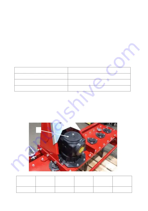
Check gear oil by unscrewing and removing filler plug/breather (1). Use a 
dipstick or similar to check the oil level and ideally this should be half full. 

The gearbox can be topped up using the filler plug on the top of the unit. 
Then replace filler plug/breather (1)
Use an oil pump to remove old oil and any debris when changing oil. 

Oil Change 

#1 

Oil Change 

#2 

Oil Change 

#3 

Oil Change 

#4 

Oil Change 

#5 

Oil Change 

#6 

/       / 

/       / 

/       / 

/       / 

/       / 

/       / 

Summary of Contents for WPH Series

Page 1: ...Owner Manual Winton Power Harrow WPH Series IMPORTANT Read all instructions before using this attachment ...

Page 2: ... attachment is subsequently sold The manufacturer continually seeks advancements in its product design and quality Therefore while this manual contains the most current product information available at the time of printing there may be minor discrepancies between your attachment and this manual If you have any questions concerning this manual please consult your local dealer Model number WPH130 WP...

Page 3: ... those securing blades Regularly check condition of blades belts and wearing parts Immediately repair replace any damaged or worn parts 7 Ensure all safety guards are in good condition and securely in place 8 Always keep the PTO output from the tractor at 540 rpm Reduce the speed when working on hillsides rough terrain Stop the engine immediately if excessive vibration occurs 9 Switch off the PTO ...

Page 4: ...ive shaft 5 Add extra weights to front of tractor or wheel weights if required 6 Ensure all safety guards doors covers are securely in place 7 Keep spectators at a safe distance before operating machinery Post use Regular Checks Caution Components can be hot after operation Allow attachment to cool before performing checks Pay attention to any sharp pointed parts and use suitable tools when servic...

Page 5: ...Blade Layout page 20 Attaching Resizing PTO Shaft page 21 Winton Product Warranty page 23 Contents Specifications Model WPH130 WPH170 Weight 274kg 345kg Working Width 130cm 170cm Number Of Blades 12 6L 6R 16 8L 8R Blade Type Tilling depth 18cm 18cm Recommended Tractor HP 25 40hp 36 50hp Width 170cm 210cm Depth 120cm 120cm Height 95cm 95cm Drive Type Gears Gears PTO Speed 540 RPM 540 RPM PTO Shaft ...

Page 6: ...e pins and linch pins 2 Attach the top linkage arm to the top link point on the power harrow and tractor Extend the linkage arm to ensure the power harrow sits level and the a frame is vertical 3 Set the working depth by lifting the tractor s hydraulic arms to increase or decrease the blade tine depth as required 4 Check the PTO shaft s grease points and apply grease if needed Attach the PTO drive...

Page 7: ...40 rpm If struggling on harder denser soil types then lower the speed or raise the working depth Adjust the rear mesh roller for a different finish 3 After a few metres stop and check the result and make any adjustments Adjust the rear mesh roller for a different finish Keep the worked soil to the driver s right side 4 Ensure the power harrow is at a complete standstill before raising it from the ...

Page 8: ...wise Each blade tine unit comprises of a tine flange guard plate two tines bearing housing bearing and connecting elements The tines are mounted underneath the guard plate and serve to loosen the soil They are secured with bushings washers bolts and lock nuts 1 Remove fastening bolts and nuts 1 there are 2 bolts per blade 2 Replace damaged bent worn or blunt blades Ensure the sharp side of the new...

Page 9: ...set the tiller at a higher setting to reduce the working depth Use the power harrow in two or more passes to increase the working depth if required The roller has 7 set holes with a pin and R clip holding the roller in place on either side Adjust the height by removing pin and R clip on both sides and set to desired height Remove pin and R clip 1 on both sides of the roller bracket Move the roller...

Page 10: ...Always follow manufacturer s instructions for oils and lubricants Gear Oil Grade 80w90 gear oil or equivalent Gearbox Oil Level Approx 1 5 litres to level plug First Oil Change 120 hours use Oil Change Frequency 250 hours yearly whichever is first Check gear oil by unscrewing and removing filler plug breather 1 Use a dipstick or similar to check the oil level and ideally this should be half full T...

Page 11: ... oil types Always follow manufacturer s instructions for oils and lubricants and dispose of oils correctly and safely Ensure the machine is on a flat level surface when checking oil levels The reservoir spans the length of the machine so if machine is not level you will be unable to identify the correct amount of lubricant in the reservoir Unscrew and remove the filler cap 1 Use a dipstick or by e...

Page 12: ...ipe grease nipples with a clean cloth before greasing to avoid injecting any dirt grit Press grease into each grease nipple 3 to 5 times ideally with a hand held grease gun for the best results If grease nipples will not take grease remove and clean thoroughly including the lubricant passageway Replace repair broken grease points immediately Grease both grease points on either end of the PTO shaft...

Page 13: ...on the tine fixings Check oil levels every 4 hours and prior to use Ensure lubricant is topped up when needed Replace any oils as per the schedule Check condition of PTO shaft replace if worn damaged immediately Regularly clean the machine remove debris from moving parts Do not spray water on bearings if using a high pressure washer Check bearings on blade rotors are working smoothly by running th...

Page 14: ...14 Parts Diagram 1 ...

Page 15: ... 24 32 11 503010048 GB6170 M14 Nut M14 24 32 12 506030038 GB93 14 Washer 14 24 32 13 706590022 LXG170 110 Blade fixing seat 5 7 14 706590021 LXG170 109 Blade left 6 8 15 501010768 GB5782 M14X60 Bolt M14x60 24 32 16 805680006 LXG130 011 Gear box drive blade seat assembly 1 17 503010762 DIN985 M10 Six corner locknut M10 77 18 1 805680002 LXG130 018 1 Protection bar weldment 130 1 18 2 806590006 LXG1...

Page 16: ... 16 6 36 503010049 GB6170 M16 Nut M16 6 37 509010009 GB1152 M10X1 Pressed oil cup M10x1 8 38 703070084 CBW 00 011 Bolt 2 39 510015240 JB982 16 Combined oil seal 16 2 40 706590015 LXG170 102 Rotor support bracket cover 5 7 41 1 805680001 LXG130 015 Top panel cover plate 130 1 41 2 806590003 LXG170 015 Top panel cover plate 170 1 42 706590034 LXG170 132 Rotor seal spacer 8 43 806590004 LXG170 016 Ro...

Page 17: ...30 Bolt M10x30 10 60 1 805680003 LXG130 024 MESH Roller 130 mesh style 1 60 2 806590008 LXG170 024 MESH Roller 170 mesh style 1 61 511040011 UCF205 Roller bearing UCF205 2 62 501011115 GB5783 M10X40 Bolt M10x40 8 63 1 805680004 LXG130 025 Roller bracket 130 1 63 2 806590011 LXG170 025 Roller bracket 170 1 64 706590028 LXG170 123 Blade Right 8 65 806590005 LXG170 017 Left roller connecting bracket ...

Page 18: ...18 Parts Diagram 2 ...

Page 19: ...gear 1 14 511022658 GB276 6311 Bearing 6311 1 15 510020390 CFW 50X68X8 Oil seal 50x68x8 2 16 706590038 LXG170 138 Bush 1 17 706590011 1G 150 01 114 Gasket seal 1 18 806590012 LXG170 026 Gearbox plate 1 19 506030036 GB93 10 Washer 10 8 20 505011429 GB70 1 M10X25 Bolt M10x25 8 21 706590037 LXG170 136 Gearbox drive shaft 1 22 706590036 LXG170 135 Bush 1 23 706590035 LXG170 133 Output gear 1 24 511022...

Page 20: ...ernating clockwise or anti clockwise from the main drive blade seat 1 under the gearbox Each blade carrier has the same directional blade fitted So either 2x left blades or 2x right blades are bolted on dependent on whether the carrier spins clockwise or anti clockwise underneath the machine 1 ...

Page 21: ...curely in the groove on the PTO Always replace worn damaged PTO shafts Most PTO driven attachments are supplied with a standard size PTO shaft which often requires resizing Firstly attach the rotovator to the tractor without the PTO shaft then raise the linkage so the PTO shaft is level horizontal Measure the length between the tractor PTO and the rotovator s shaft If the compressed closed PTO sha...

Page 22: ...ained according to the Owners Manual Warranty is carried out on a return to reseller manufacturer basis and excludes any labour delivery collection costs Exclusions Wearing parts are excluded including but not limited to blades belts and bearings Modification of the product in any way will cease the manufacturer s warranty The machine is warranted for one year to the original purchaser resale with...

Page 23: ...23 Notes ...

Page 24: ...Published August 2021 ...

Reviews: