


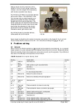


Instructions condensing Air heaters type XR version XR-GB-4001-a
Page 23/27
20K@25°C
22°C
L
N
F1
20K@25°C
20K@25°C
J9- 1
J9- 3
J9- 2
J9- 4
J6- 1
J6- 8
J6- 2
J6- 9
J6- 3
J6- 10
J6- 4
J6- 11
J6- 5
J6- 12
J6- 6
J6- 13
J7- 1
J7- 2
J7- 3
J7- 4
J7- 5
J7- 6
J7- 7
J7- 8
J7- 9
J7- 10
J12- 1
J12- 4
J12- 2
J12- 5
J12- 3
J12- 6
J8- 1
J8- 2
J6- 7
J6- 14
T1
J2- 1..6
J1- 1
J1- 5
J1- 2
J1- 6
J1- 3
J1- 7
J1- 4
J1- 8
J3- 2
J3- 6
J3- 1
J3- 7
J3- 3
J3- 8
J3- 4
J3- 9
J3- 5
J3- 10
J4- 2
J4- 3
J4- 5
J4- 4
J4- 1
J4- 6
J5- 1
J5- 2
J5- 4
J5- 3
4 3
1
2
J25
LED RESET
4 3
1
2
4 3
1
2
PE
L on/off
12
11
N
L
5
4
J17
N
L
N
L
~
~
+
-
Rect.
7
6
dP
RT
dT
dT
11
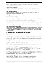
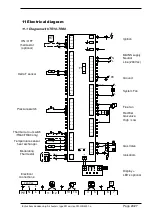
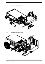
Electrical diagram
11.1 Diagram with TR10-TR80
Ignition
MAINS supply
Neutral
Line (230Vac)
Ground
System Fan
Flue fan
Rectifier
Gas valve
High / Low
Gas Valve
Ionisatiom
D
LED’s optional
ON / OFF
thermostat
(optional)
Delta T sensor
Pressure switch
Thermal cut out switch
(TR60/TR80 only)
Temperature sensor
heat exchanger
Modulating
Thermostat
Electrical
connections:
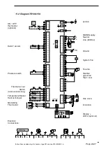
7
4
PE
L
N
5
6
RT
N
L
230 Vac
L
N
11
12
22°C
13
14
N
L


