


Instructions condensing Air heaters type XR version XR-GB-4001-a
Page 11/27
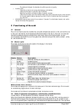
ON/OFF thermostat
The heater cannot be controlled with a simple on/off thermostat.
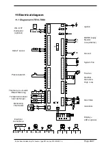
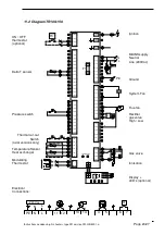
In all cases the communication between heater and thermostat is based on a two wire, low-
voltage connection. In the appliance the wire for the thermostat has to be connected to
connection 4 and 5 (see also electrical wiring diagram) Attention: This also needs a change in
the settings on the print board.
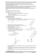
4.4.3 Thermostat installation
When mounting the thermostat, take attention to the following items:
•
Mount the thermostat in a place where the air can circulate free pass the thermostat. Take
notice that the sun does not shine directly upon the thermostat (in the winter). Do not
place the thermostat on a cold wall. Place the thermostat on an inner wall free from
draught.
•
Never place the thermostat within the throw of the heater.
•
Never mount the thermostat near aerials of internal communication networks. These emit
radiation that could lead to disturbance of the thermostat. Always keep some meters
distance.
•
In all cases the communication between the heater and the thermostat is based on a two
wire, low-voltage connection. In the appliance the wire for the thermostat has to be
connected to connection 4 and 5 (see also electrical wiring diagram).
Cable specification: signal cable, 1x2x0,8 (shielded and twisted)
Maximum length 250m.
If the cable is chosen too thin, the signal will become too poor. If the cable is not shielded and
twisted the signal might become disturbed in an EMC unfriendly environment.
Keep the thermostat cable separated from mains cables. Connect the earth shield of the cable
only to the earth terminal in the heater.
If these guidelines are not followed it may result in malfunction of the installation or worse, it
could damage the thermostat or the electronics in the heater.
4.4.4 Fuse
On the heater control board there is 1 fuse. See electrical wiring diagram.
F1 and in the power supply of the heater. Replace the fuse only by a fuse of the same type, 5AT
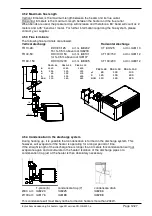
4.5 Air intake / combustion products discharge
Check for compliance with local / national regulations.
Only the described flue material may be used. This goes for the roof or wall terminal and also
for the piping between the heater and the terminal. Only so the installation is approved.
Do not use terminals for condensing appliances. This can lead to water inside the flue system.
In some cases the roof terminal has to be at least 0,5m above roof level (depending on local
regulations).
Pay attention on fresh air ventilation openings on the building. There are local distance
restrictions on placing a flue terminal near the ventilation openings.
4.5.1 Flue material
It is only allowed to use CE marked flue material from the manufacturer Muelink & Grol (M&G)
and Burgerhout, type Alu-fix temperature class minimum T200. These Flue systems can be
bought at your supplier.
Only use one flue pipes from the same diameter as the flue spigots on the heater.
Different manufacturers have different connections systems from the flue pipes. It is not allowed
to combine systems from different manufacturers.


