background image

M

ULTIMAX 300                                                                        

Chapter 3: OPERATION 

26 


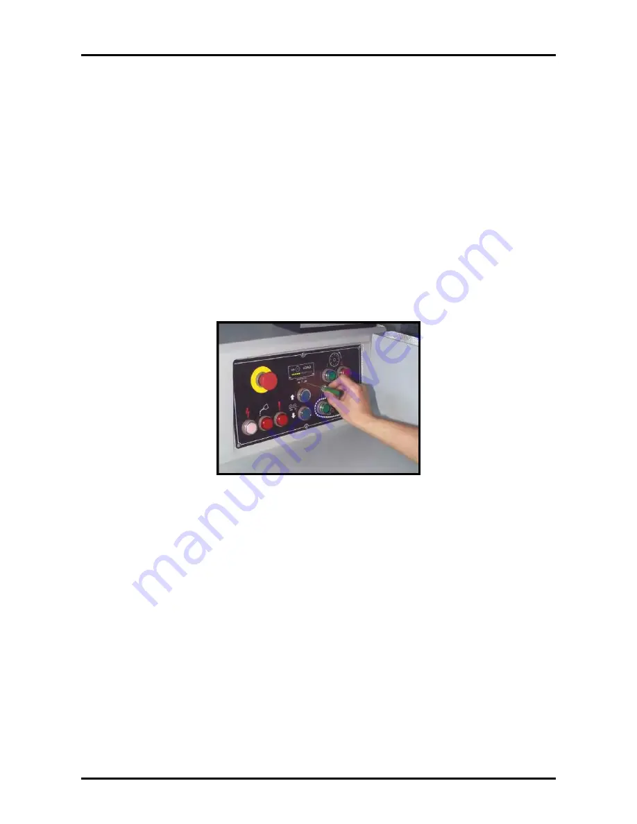
According  to  the  quantity  and  the  sharpness  of  saw  blades,  feed  speed  and  the 

smooth  demand  on  the  ripping  surface,  the  operator  can  adjust  the  sensitivity 
micro-adjustment  button  of  motor-load  to  a  proper  position  (to  increase  the 
sensitivity  by  turning  it  in  a  clockwise  direction;  to  reduce  the  sensitivity  by 
turning it in a counter-clockwise direction; the range of mirco-adjustment from the 
direction of eight clock to four clock). If the sensitivity is adjusted to be too sharp, 
the feed chain will often stop easily; if it is adjusted to be too dull, this device can 
not  perform  the  protection  function  of  the  feed  chain  auto-slowdown.  After  used 
the machine for a period of time, if the indication lamp is often in the postion of 
close to yellow lamp or red lamp, it means the workload is overloaded. There are 3 
ways to solve: 


1.


The saw blades are worn, must replace with new saw blades. 

2.


Slow down the feed speed. 

3.


Reduce the quantity of saw blades. 


Summary of Contents for MULTIMAX 300

Page 1: ...t thoroughly read this manual before operation Keep this manual for future reference Henrik Winter Holztechnik GmbH Druckereistr 8 04159 Leipzig Tel 49 0 341 4619021 Fax 49 0 341 4618358 Funk 49 0 171 2820443 Em il info winter holztechnik de Internet www winter holztechnik de ...

Page 2: ......

Page 3: ...cifications Drive Motor Q TY HP Volt Hz Saw arbor motor 1 set 30 40 50 60 Feed motor 1 set 2 4 8P 3 4P Pressure rollers elevation motor 1 set 1 2 Belt specifications Shaft 5 6 8 9 pcs triangular belt 3V710 SPA 1957 SPA 2000 Conveyor belt accelerator 1 pc ribbed belt 1922V403 2 pcs triangular belt A42 ...

Page 4: ...ssional repair or maintenance contact your local dealer giving him the following information Model number Serial number Date of purchase Precise details of the fault or problem Your dealer can provide parts and service authorized by head office ensuring safe and efficient operation A list of addresses and telephone numbers of dealers worldwide can be found in the appendix at the back of this manua...

Page 5: ... 2 INSTALLING AND REMOVING BLADES 18 3 3 CHECKING SAFETY DEVICES 20 3 4 STARTING THE BLADES 21 3 5 FIXING THE SAW ARBOR IN POSITION 21 3 6 ADJUSTING THE HEIGHT OF THE PRESSURE ROLLERS 22 3 7 ADJUSTING THE POSITION OF THE FENCE 23 3 8 STARTING THE CATERPILLAR CHAIN 24 3 9 INPUT OF MATERIAL 25 3 10 SAFETY DEVICE FOR SAW ARBOR 27 CHAPTER 4 MAINTENANCE 28 4 1 CLEANING 28 4 2 LUBRICATION 30 4 3 ADJUSTM...

Page 6: ......

Page 7: ...m on this machine and the power used is 30 50HP The work piece that fed by chain takes a large of reacting force during cutting If the pressure rollers can not hold down the work piece properly the work piece will be kick back anytime and hurt the operator To prevent the accident when make a change on thickness of wood must adjust the pressure rollers to the proper position refer to Ch 3 6 As the ...

Page 8: ...ed two or more planks of wood into the machine at the same time Never use wood of thickness greater than 110mm or length shorter than 300mm When making a change in the thickness of wood the height of the pressure rollers must be readjusted to the proper position This is to ensure the rollers maintain a firm grip so that the wood being cut cannot come flying out If using planks that have not had th...

Page 9: ... of saw arbors turns Checks should be made regularly to ensure that there are no foreign objects jammed in the gaps between the feed chain An air gun should be used daily to remove sawdust from these gaps Make certain that the power of the machine is disconnected from the power source before effecting any cleaning lubrication maintenance repair adjustments or part replacements The operator should ...

Page 10: ...LATES INDICATOR DESCRIPTION DO NOT move unless change saw blade or adjust blade Make certain that blades are installed with the teeth pointing in the same direction as the rotation of saw arbor turns Warning Danger Safety Instructions Warning electricity ...

Page 11: ...MULTIMAX 300 Chapter 1 INTRODUCTION 5 INDICATOR DESCRIPTION The machine MUST be with the grounding installation below 10 Ω Danger Warning Warning Warning ...

Page 12: ...MULTIMAX 300 Chapter 1 INTRODUCTION 6 INDICATOR DESCRIPTION Warning Warning Operator MUST follows all safety principles and warning stickers on machine ...

Page 13: ...lade bore 70 mm Saw arbor diameter 50 mm Saw arbor speed 3800 R P M Saw arbor motor 30 40 50 or 60 HP Feed motor 2 HP 4P 8P Variable feed speed Belt driven type 7 5 30 M min Feed motor c w frequency inverter Option 3 HP Variable feed speed c w frequency inverter Option 2 5 24 M min Hold down roller elevating motor 1 2 HP Dust hole diameter 2 150mm or 1 200mm Table height from floor 850 mm Table ar...

Page 14: ...ee safe operation A specially designed width safety limit switch prevents over wide workpieces from damaging the cover The maximum infeed workpiece width is 600mm AUTOMATIC FORCED LUBRICATION SYSTEM Centralized forced lubrication ensures a proper oil film on the caterpillar chain and rails If there is insufficient oil in the oil tank the warning lamp lights up and the caterpillar chain stops runni...

Page 15: ...nt guard 2 Saw arbor elevating handle 3 Holddown roller housing elevating motor 4 Support rod for saw sleeve 5 Control panel 6 Fence 7 Speed changing hand wheel for feeding 8 Fence clamp handle 9 Position guide bar for cutting width 10 Anti kickback fingers 11 Feed chain cover ...

Page 16: ...utton 3 Blade STOP button 4 Blade START button 5 Power indicator 6 Feed chain lubricant insufficient indicator 7 Protections open indicator 8 Pressure rollers DOWN button 9 Pressure rollers UP button 10 Feed chain START button low speed 11 Feed chain STOP button 12 Feed chain START button high speed ...

Page 17: ...r s load 4 Sensitive adjustment swith of saw arbor s load 5 Blade star button 6 Blade stop button 7 Power indicator 8 Caterpillar chain lubrication oil insufficient indicator 9 Protection open 10 Pressure rollers DOWN button 11 Pressure rollers UP button 12 Caterpillar chain START button 13 Feed speed adjustment switch 14 Caterpillar chain STOP button ...

Page 18: ...MULTIMAX 300 Chapter 1 INTRODUCTION 12 Machine size ...

Page 19: ...ny signs of having been dropped or mishandled If the answer to either of these questions is yes please contact your dealer immediately and the matter will be handled by qualified technicians 2 2 MOVING THE MACHINE The machine may be moved in two ways 1 Firstly remove the bolts which fix the machine to the base of the crate Secondly lift the machine up using a strong cable as shown below 2 Pick up ...

Page 20: ...and Y shafts and horizontal is less than 0 3mm m After completion of the leveling process be certain to re tighten the foundation nuts 2 4 POWER CONNECTION The power source should be connected by a qualified electrician All wiring must be conform to international safety guidelines choose a most suitable size of cable subject to the voltage and mounting motors A suitable breaker should be installed...

Page 21: ... the power indicator will light up 2 Observe the pressure roller housing If the housing goes up while push the pressure roller housing rising button it means the power wiring is correct If the housing goes down while push the rising button Shut Off the Power Immediately to stop the machine After reversing two 2 phase cables restart and test run again 3 When make sure the pressure roller housing an...

Page 22: ...OLLECTING APPARATUS Use a 6 dia flexible hose to connect the two Ø150mm dust outlets to the dust collector The minimum air consumption for one 6 dia flexible hose can not be less than 1782 m3 hr The total consumption of this machine can not be less than 3564 m3 hr ...

Page 23: ...g the machine must install with the optional short stock cutting device Refer for the Appendix I Normal short pressure plate for cutting long piece To change same type of pressure plate loose the fixing nut do not need to take the nuts off completely then take out or insert the pressure plate After insert the pressure plate Be sure to lock the nuts to fix it on the bracket The pressure plate must ...

Page 24: ...ontact faces of saw sleeve and saw arbor the inner side of the sleeve and the surface of the saw arbor by clean cloth Any wood chips or foreign substances objects sticks on them will cause sway and vibration when the saw blades are running These sway and vibration will make the sawn wood not precise Further more cause the defect of machines accuracy 3 Turn upward the lock pin of the saw arbor lift...

Page 25: ...ex part B in the following picture of the rear of the saw arbor inserts to the groove A in the following picture of the saw sleeve when put the saw sleeve assembly on the saw arbor 5 Use the following three special wrenches to lock saw sleeve nut and saw arbor nut ...

Page 26: ...h the special sleeve nut wrench and saw arbor lock wrench to release the nuts of the saw arbor and the saw sleeve After that the saw blades and spacers can be taken off 2 Before installing the new saw blades and spacers on the sleeve make sure to clean up the surfaces of them Also make certain that the saw blades are in the same size and installed with sawteeth pointing in the same direction 3 Tig...

Page 27: ... have been installed completely start the saw blades to let the saw arbor rotate Turn the saw arbor elevating handle slowly in a counter clockwise direction until the saw blade diameter indicator shows the scale of saw blades diameter e g when use 12 diameter saw blades adjust the indicator to the scale of 12 After positioned be sure to insert the fixed pin of saw arbor elevating handle to the nea...

Page 28: ... wood to be cut is 100mm the height of pressure rollers should be adjusted to the position of the scale indicating 97 98mm To prevent screws of pressure plate from being broken when the wood is in irregular shape the height of pressure rollers should be raised to the position of the scale indicating 110mm then lower to 97 98mm Notice When the thickness of the same wood piece is not even or over be...

Page 29: ... fence is positioned by locking handle There is a distance between the fence and the first saw blade and the length of this distance is depending on how neat of the edge of the wood to be cut It needs more distance between them If the edge of the working material is very irregular ...

Page 30: ...e number of the blades Also adjust the speed changing handwheel to get a proper feed speed To switch over between Low speed and High speed feed chain start buttons the operator must press the feed chain STOP button at first EQUIPPED W ELECTRICAL AMPERAGE DISPLAY Press the caterpillar chain start button to make the caterpillar chain move and adjust the feed speed adjusting button To adjust the feed...

Page 31: ...pping the wood to understand the load of the saw arbor motor Use the feed speed changing wheel to adjust to the optimum feed speed Refer to the table for the suitable voltage and horse power on the following table saw arbor motor 220 V 380 V 415 V 440 V 40 HP 100 A 60 A 55 A 50 A 50 HP 125 A 75 A 66 A 62 A 60 HP 150 A 85 A 80 A 74 A The amperage shown on the control panel can not exceed the value ...

Page 32: ...the range of mirco adjustment from the direction of eight clock to four clock If the sensitivity is adjusted to be too sharp the feed chain will often stop easily if it is adjusted to be too dull this device can not perform the protection function of the feed chain auto slowdown After used the machine for a period of time if the indication lamp is often in the postion of close to yellow lamp or re...

Page 33: ...hat results from the running saw arbor while opening the cover How to operate 1 Push the Emergency Stop Switch or Saw Blade Stop Button during saw arbor running At this moment the sensor will detect the saw arbor running After the saw arbor stops completely the indicator lamp will be on 2 When the indicator lamp is on it means the saw arbor stops completely Be sure to press the indicator button an...

Page 34: ...on it will cause serious wear on feed chain The operator must clean up the sawdust on every chain link completely Open feed chain safety cover you can see clearly there are one clean brush and six lubricating inlets for feed chain They are the important components to protect and prolong the lifespans of feed chain and rails The saw dust can not accumulate on the clean brush and lubricating inlets ...

Page 35: ...ime to ensure the maximum efficiency is being maintained At the same time as performing the machine s regular lubrication checks clean away dust and saw dust from all parts of the machine The operator must make a maintenance registered book Do the time maintenance exactly to protect the machine ...

Page 36: ...suggest using the following lubricants Name Lubricant ISO specification VG 68 Viscosity cst 40 68 Brand Mobil Vectra No 2 ESSO Febis K68 SHELL Tonna T68 The storage of lubricant must take care of clearance Never use the polluted lubricant Prohibit from using recycled oil Be sure to use the good quality of lubricant to ensure an effective lubrication on the machine running We suggest using the lubr...

Page 37: ...e Name Grease Use for Bearing Viscosity cst 40 NLGI NO 2 Brand SKF LGLT2 Mobil Mobillux 2 ESSO Estan No 2 SHELL Alvania No 2 The inlets for adding grease are shown in the diagrams below 1 Open the door of saw arbor There are two grease inlets located on the upper of outer shell of saw arbor Also there is a grease inlet on the elevating nut of pressure rollers housing 2 Open the back door of the ma...

Page 38: ...igh temperatures and large power loss due to agitation For information about internal space volume of bearings see Table 4 2 2 For an example illustrating the difference in bearing temperature increase due to lubrication method see Figure 4 2 1 Table 4 2 1 Main Grease Used for Machine Tool Bearings Grease brand Manufacturer Base oil Thickener Recommend ed operation temperature range Main applicati...

Page 39: ...10 3 5 6 7 5 08 40 5 2 7 8 13 0 7 2 9 5 09 45 5 7 10 2 15 4 9 0 12 8 10 50 6 2 10 7 18 6 9 7 8 0 13 8 11 55 15 9 25 9 14 0 12 0 19 6 12 60 17 0 33 2 15 0 13 0 20 7 13 65 18 2 39 1 16 0 14 0 21 8 14 70 27 7 45 2 22 0 19 0 30 4 15 75 28 7 49 4 23 0 20 0 32 9 16 80 32 1 59 0 30 0 27 0 46 3 17 85 36 3 73 5 31 0 28 0 62 9 18 90 49 2 93 1 40 0 38 0 62 9 19 95 53 0 117 42 0 40 0 64 5 20 100 55 1 135 43 4...

Page 40: ...4 3 8 25TAB06 4 8 30TAB06 4 8 35TAB07 5 8 40TAB07 5 8 40TAB09 14 45TAB07 6 5 45TAB10 15 50TAB10 16 55TAB10 16 55TAB12 19 60TAB12 19 3 Ball Screw Support Bearing TAF Series Internal Space Volume Bearing no Internal space volume cc each 25TAF06 9 3 30TAF07 14 35TAF09 26 40TAF09 26 40TAF11 45 45TAF11 45 50TAF11 45 60TAF13 71 60TAF17 150 80TAF17 150 100TAF21 282 120TAF03 473 ...

Page 41: ...speed reducer should be cleaned and the oil for the gears should be changed Thereafter the oil for the gears should be changed after every 2500 working hours To do this first remove the protective cover from the feed chain speed reducer Then open the oil inlet cover and turn open the oil release screw When all the old oil has drained out close the oil release screw again Add SAE 90 lubricating oil...

Page 42: ...xed nut by turning in a clockwise direction The threaded rod can then be turned until the desired position is reached loosen by turning in a clockwise direction tighten in a counter clockwise direction After finish the adjustment the fixed nut must be tightened again by turning in a counter clockwise New belts should be re tightened after the first 4 working hours After 8 working hours they should...

Page 43: ...ring or splitting it should be replaced as described below 1 Start up the caterpillar chain turn the speed changing handwheel to its slowest position and then switch off the power supply 2 With the power turned off rotate the speed changing handwheel to its fastest position 3 Remove the old belt and replace it with a new ribbed belt of specification 1922V403 Install with electrical amperage displa...

Page 44: ...he new belts should be re tightened after the first 4 working hours After 8 working hours they should be re tightened again Thereafter the belts should be inspected and adjusted after every 200 working hours If the belts show the signs of wear they should be replaced by new belts of the same brand and from the same production batch Old and new belts should never be used together ...

Page 45: ...he lubricator The upper knob is for adjusting the interval time between the two lubrications minute the lower knob is for adjusting the lubrication time per pump second 2 The user can adjust oil supply according to operation situation of the machine the lubricator has been set at pumping lubricant for 5 seconds every 5 minutes ...

Page 46: ...just the short pressure plate 1 Firstly take off the long pressure plate and the pressure plate fixed support from the housing No need to take off the rear mounting bracket of pressure plate which is one the left side 2 Install the short pressure plate on the pressure roller housing 3 Arise the pressure roller housing to 30mm height see the scale ...

Page 47: ...l 3 pcs that locate on the pressure plate fixed support to make the lowest position of the pressure plate to be apart from the machine table for 37mm The drop height between the surface of feed chain and machine table is 7 mm 5 Fasten the set screws and nuts after adjustment to finish the installation ...

Page 48: ...ure plate OPTION 1 Arise the pressure roller housing to a proper height 80mm 2 Take off the left and right shields and the short pressure plate 3 Lock the rear mounting bracket of pressure plate to the pressure roller housing with screws 4 Fasten the pressure plate fixed support to the pressure roller housing ...

Page 49: ...acket of pressure plate and the pressure plate fixed support 6 Descend the pressure roller housing to zero position go home 7 Loosen 4 pcs of nuts for the rod of support spring set for the pressure plate CAUTION The pressure roller housing can not be descended to go home while the anti kickback fingers have inserted into chain block ...

Page 50: ... 8 Then adjust these 4 pcs of nuts until the long pressure plate is away from the surface of feed chain for about 1mm near to the thickness of a steel ruler 9 Fasten the nuts after adjustment then install left and right shields back to the machine to finish the installation ...

Page 51: ...MULTIMAX 300 Appendix I Installation and Adjustment of Pressure Plate 45 The pressure plate must be made of solid and complete wood according the following diagram optional ...

Page 52: ......

Page 53: ...A A 4 8 3 2 16 1 14 12 10 5 7 10 13 17 18 15 9 11 2 2 4 2 PAGE BM31 03 0 ...

Page 54: ...PAGE BM31 05 0 BM31 05 0 BM31 05 0 BM31 05 0 2 10 9 4 8 2 6 5 11 1 3 2 4 3 3 7 12 2 ...

Page 55: ...8 4 1 7 5 6 3 12 10 9 11 2 2 2 2 2 3 4 3 PAGE BM31 10 0 ...

Page 56: ...PAGE AM31 010 0 52 212 106 106 4 3 1 2 5 ...

Page 57: ...4 3 7 11 6 10 5 1 2 8 9 3 2 PAGE AM31 020 0 ...

Page 58: ...5 12 20 3 4 1 2 17 15 14 9 6 7 8 13 19 16 10 11 21 18 2 2 4 7 4 2 3 2 PAGE AM30C 121 0 ...

Page 59: ...11 10 13 14 12 15 16 9 8 7 5 4 3 2 1 6 3 3 PAGE AM30C 130 1 AM30C 130 1 AM30C 130 1 AM30C 130 1 ...

Page 60: ...PAGE AM31 100 0 1 6 7 8 9 10 2 3 4 5 13 12 11 5 5 5 5 2 4 4 4 4 ...

Page 61: ...PAGE AM31 121 0 16 6 15 13 10 7 1 20 17 3 2 9 8 4 19 5 11 18 12 14 3 4 4 4 4 3 2 3 2 ...

Page 62: ...PAGE AM12 100 0 1 2 3 4 5 2 2 2 ...

Page 63: ...4 4 4 5 4 9 8 3 2 2 2 1 2 7 8 2 2 6 12 10 11 2 PAGE BM30C 210 0 BM30C 210 0 BM30C 210 0 BM30C 210 0 ...

Page 64: ...PAGE BM30C 231 0 BM30C 231 0 BM30C 231 0 BM30C 231 0 2 4 1 2 3 3 ...

Page 65: ...1 2 5 PAGE BM30C 240 0 BM30C 240 0 BM30C 240 0 BM30C 240 0 MRS 300C MRS 300C MRS 300C MRS 300C MODEL ...

Page 66: ...8 7 4 3 5 6 1 4 7 3 3 2 PAGE BM31 26 0 ...

Page 67: ...7 22 35 5 6 34 2 23 3 9 27 28 2 37 4 32 17 26 18 30 19 20 21 25 24 11 8 29 10 1 16 13 14 36 2 2 12 3 33 4 31 4 15 PAGE AM30C 030 0 ...

Page 68: ...16 14 7 2 2 4 105 3 75 5 29 24 11 15 17 10 8 13 12 18 19 21 6 25 2 1 22 23 2 2 4 4 4 4 2 5 5 6 6 3 9 20 5 29 4 28 2 27 2 4 30 2 PAGE AM30C 040 3 AM30C 040 3 AM30C 040 3 AM30C 040 3 ...

Page 69: ...50 1 53 55 2 24 11 28 31 30 32 33 45 44 52 49 37 2 15 38 40 35 36 42 41 34 39 43 50 46 16 3 1 26 19 6 7 5 17 18 12 21 54 8 9 14 13 20 10 19 2 2 2 4 8 4 2 2 10 8 2 2 2 2 4 16 4 4 38 39 23 4 2 2 8 8 4 16 16 8 8 8 8 27 4 2 29 2 2 47 4 2 48 2 51 2 22 56 ...

Page 70: ...PAGE AM30C 080 0 AM30C 080 0 AM30C 080 0 AM30C 080 0 3 5 6 4 17 3 12 13 14 16 28 27 26 2 30 29 1 15 9 21 2 6 6 10 8 24 11 20 19 18 2 25 23 2 8 6 4 22 8 4 4 2 2 2 7 2 ...

Page 71: ...PAGE AM30C 110 0 4 24 9 27 8 2 18 4 13 22 16 4 25 14 17 7 5 6 3 10 11 2 26 19 2 4 2 4 2 11 9 15 1 2 23 2 20 2 21 28 2 29 4 31 12 30 9 ...

Page 72: ...PAGE AM30C 150 0 AM30C 150 0 AM30C 150 0 AM30C 150 0 6 3 2 11 12 5 7 1 2 3 4 2 2 9 4 10 6 8 4 3 ...

Page 73: ...PAGE AM30C 261 0 4 2 1 8 3 10 6 7 4 4 5 9 5 4 11 2 ...

Page 74: ...1 2 3 4 5 6 4 4 PAGE AM31 303 0 ...

Reviews: