


USER MANUAL
CHAPTER 2
HARDWARE INSTALLATION
- 24 -
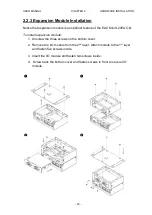
2.3 Connecting the Power
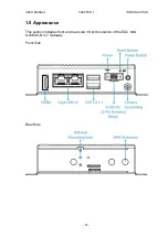
The DC power supply connector of the EAC Mini IoT Gateway is on the front
panel. The DC power input for the EAC Mini allows a voltage input range from 9
V DC to 30 V DC.
WARNING!
Ensure voltage and polarity is compliant with the DC input.
Improper input voltage or polarity can cause system damage.
2.3.1 Connecting the Power
Connect EAC Mini to 9-30V DC. The power source can either be from a power
adapter or an in-house power source. Front power LED indicator indicates the
power status of the device.
2.3.2 Chassis Grounding
EAC Mini provides EMI protection and a stable grounding base. Use chassis
grounding point located on the front.
Summary of Contents for EAC Mini IL20EAC-N
Page 1: ...IoT Gateway Intel Apollo Lake N3350 1 1 GHz EAC Mini IL20EAC N User Manual Version 1 0 ...
Page 2: ......
Page 37: ...USER MANUAL CHAPTER 4 INSYDE UEFI BIOS SETUP 35 4 2 2 2 GOP and IGD Configuration ...
Page 41: ...USER MANUAL CHAPTER 4 INSYDE UEFI BIOS SETUP 39 PCI Express Root Port ...
Page 43: ...USER MANUAL CHAPTER 4 INSYDE UEFI BIOS SETUP 41 4 2 2 4 SATA Drives ...
Page 57: ...USER MANUAL CHAPTER 4 INSYDE UEFI BIOS SETUP 55 4 2 3 Boot Menu ...
Page 59: ...USER MANUAL CHAPTER 4 INSYDE UEFI BIOS SETUP 57 4 2 3 1 Boot Type Order 4 2 3 Exit Menu ...


