Various wiring diagrams
____________________________________________________________________________
Smoke control unit - WSC 304 01
13
Page 1: ...Commisioning Maintenance www WindowMaster com WindowMaster A S Skelstedet 13 2950 Vedb k Danmark Tel 45 4567 0300 Fax 45 4567 0390 WindowMaster GmbH Zum Bache 4 32549 Bad Oeynhausen Deutschland Tel 49...
Page 2: ...onnection Leave the insulation of the power supply cable in place up to the mains terminal Manufacturer s declaration The central control system is exclusively designed for the automatic closing of sm...
Page 3: ...review WSC 304 01 ____________________________________________________________________________ Smoke control unit WSC 304 01 3 Operating Accu Motor Alarm Mains Motor Smoke det SHE switch SHE display...
Page 4: ...reak glass unit are lit The yellow malfunction LED in the break glass unit flashes Resetting a trip caused by high temperature The smoke extraction system can be closed again by pressing the Reset but...
Page 5: ...ter ventilation OPEN or ventilation STOP This function is not operative if the setting potentiometer is on the right hand stop Wind rain CLOSE The actuators close when the wind rain sensor has tripped...
Page 6: ...must be specially made in the production by using a special software ASV CLOSE When ASV CLOSE is tripped all actuators automatically CLOSE An acoustic alarm signal sounds continuous sound in the break...
Page 7: ...SW2 SW 2 1 ON The smoke control system trips by a malfunction signal from the motor smoke detector or break glass unit SW 2 1 OFF The smoke control system does not trip by a malfunction signal The ma...
Page 8: ...over contact max load 60V 1A with 3 pole connection terminal for potential free transmission to the BMS panel etc 2 pole connection terminal for 2 wire BUS cable for the feedback of malfunctions in c...
Page 9: ...r the installation position Open central control and remove the housing top section door from the housing bottom section Fasten the housing bottom section in the wall cut out cut out dimension 335 x 3...
Page 10: ...ble network for smoke ventilation systems Cable system ends at the interface junction box for the actuator The flexible heat resistant connection cable of the smoke ventilation system actuator is part...
Page 11: ...Cable plan ____________________________________________________________________________ Smoke control unit WSC 304 01 11...
Page 12: ...Standard wiring diagram __________________________________________________________________________ Smoke control unit WSC 304 01 12 WLA 330 WLA331 WSA 300 WSA 310...
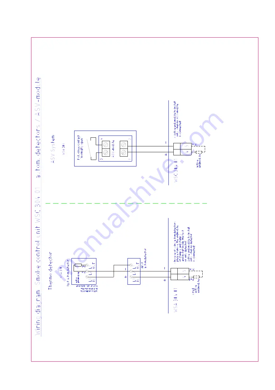
Page 13: ...Various wiring diagrams ____________________________________________________________________________ Smoke control unit WSC 304 01 13...
Page 14: ...Various wiring diagrams ____________________________________________________________________________ Smoke control unit WSC 304 01 14...
Page 15: ...e the protection film from one face of the supplied foam rubber Glue each foam rubber to the bottom side of the accumulators Connect the accumulators to the black accumulator bridge according to the w...
Page 16: ...relevant regulations b The green mains and operating LED s are OFF the yellow accumulator Led is flashing control unit in the accumulator mode The malfunction message at the break glass unit is ON c T...
Page 17: ...ystem Check fastening and clamping screws for firm seating Carry out a test run of the entire system see chapters Start up and Test Run Only have defective units repaired in our factory Only install o...