background image


Mounting 

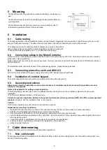
The MotorController may either be mounted horizontally or vertically on a 
wall.  
 
The MotorController is fixed to the wall 

through the back plate’s Ø4.5 mm 

mounting holes. 
 
The MotorController should be mounted in a secure location so that it 
is protected against the effects of fire and smoke. 


Installation 

6.1 

Cable routing 

The safety regulations in these guidelines must be closely followed. Regarding low power cable configuration we refer you to the 
chapter “Cable dimensioning”. The cable cross sections listed in the table of cable lengths must not be reduced.  
 
The cables are led into the MotorController’s cabinet via cut-outs in the bottom.  
When routing cables, all applicable national regulations must be complied with. 
The MotorController is supplied with a 1.2 m cable with Schuko plug. 

6.2 

Connecting cables in the MotorController 

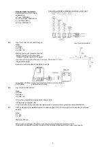
Cables are to be connected in accordance with the chapter “Connection plan for WCC 103”, the short chapters and other relevant 
paragraphs in these guidelines. 
Please ensure that connections are correctly executed - incorrect connection can lead to functional failure in the MotorController or 
external products. 


The installation must at all times adhere to the applicable regulations, standards and guidelines. 

6.3 

Connecting protective earth and 230V AC 

WCC 103 is factory-fitted with a power supply cable with a 230V Schuko plug with earth wire. 

6.4 

Installation of comfort keypad 

The comfort keypad should be mounted in a visible position and within easy reach.  

6.5 

Assembly instructions 

Always have assembly, installation, repair and maintenance of ventilation systems carried out by qualified personnel 
trained for this purpose


Rules to be adhered to for setting up and installation   

The following safety relevant rules have to be adhered to when planning the use of a ventilation system and its set-up and  
installation:   
• The Provincial Building Ordinance of the provinces 


Accident prevention regulations Adhere to the general accident prevention regulations (APR), the APR for power operated 
windows

 and doors, and the installation rules in your country.


Caution: 

If internal coverings are removed the live current parts are exposed. 


Guidelines for mounting / installation  

  the MotorController should be mounted on the wall in such a way that there is free access for service inspections 

  adhere to the installation instructions and your local energy providers  

  select the place of installation such that free access is guaranteed for maintenance purposes 

  select cables according to regulations in this instruction - take the calculation of the actuators supply cable lengths into account 

when laying the cables  

  connect the cables in accordance with the drawings provided by the manufacturer  

  route the cables in the building according to the regulations in this instruction  

  check all system functions 

Cable dimensioning 

Cables should be routed in compliance with applicable regulations. 

7.1 

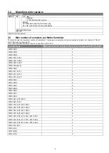
Max. cable length 

The maximum permitted cable lengths from the MotorController to the actuators, taking into account the cable cross-section, are 
shown in the following table. 

Summary of Contents for MotorController WCC 103

Page 1: ...indowMaster is a registered trademark used under license from WindowMaster International A S WindowMaster International A S Skelstedet 13 DK 2950 Vedb k WCC 103 Installation instruction MotorControlle...

Page 2: ...cting protective earth and 230V AC 6 6 4 Installation of comfort keypad 6 6 5 Assembly instructions 6 7 Cable dimensioning 6 7 1 Max cable length 6 7 1 1 Formula for calculating max actuator cable len...

Page 3: ...hat the system complies with applicable national regulations The cable cross section will depend on wire length and power consumption See chapter Cable dimensioning 1 4 Cabling and electrical connecti...

Page 4: ...rd actuators may be connected to WCC 103 Actuator type Max number 24V actuators that may be connected to WCC 103 BT WMD 820 1 3 WMD 820 2 2 WMD 820 3 3 WMS 306 309 1 3 WMS 306 309 2 2 WMS 306 309 3 3...

Page 5: ...s Primary voltage 100 240 VAC 0 85A 50 60Hz Power consumption Idling 0 5W Full load 77 W Inrush current on primary side 65A 5ms w 230V Max 6 x WCC 103 per 10A power supply group Circuit breaker C type...

Page 6: ...be mounted in a visible position and within easy reach 6 5 Assembly instructions Always have assembly installation repair and maintenance of ventilation systems carried out by qualified personnel tra...

Page 7: ...cted actuators max current consumption per motor line Note do not use the PE wire green yellow wire in the actuator cable Example Max actuator cable length with cable cross section of 0 75mm2 and 2A c...

Page 8: ...e The total current consumption connected to the motor line may not exceed 3A incl load on X7 AUX In addition to the actuators locking actuators of type WMB 8xx may also be connected The locking actua...

Page 9: ...ected to input X2 Long press 500ms open close actuator actuator runs to end stop Short press actuator stops running X3 Input for automatic control Data 3 1 Open 3 2 Close 3 3 GND 0V X3 must be control...

Page 10: ...ng on connected comfort keypad on X2 ON holding activated OFF holding deactivated Factory setting OFF Close Open all windows K1 Reset K2 FW update to be used in line with firmware updates LED 1 Yellow...

Page 11: ...Black diode off Error indicator on the yellow diode is a total errors indicator Detailed information on the error type can be decoded on the green diode Green diode LED 2 If the green diode LED 2 clos...

Page 12: ...ould only be done by the manufacturer or an authorized partner Remove all soiling from the MotorController Check fastening and clamping screws for firm seating Carry out a test run of the entire syste...

Page 13: ...ndowMaster 2020 2022 WindowMaster is a registred trademark used under the license by WindowMaster International A S WindowMaster International A S Skelstedet 13 DK 2950 Vedb k 13 WCC 103 Installations...

Page 14: ...Anschlu von Leitungen im MotorController 18 6 3 Anschluss von Schutzerdung und 230 V AC 18 6 4 Installation des L ftungstasters 18 6 5 Montage 18 7 Leitungsdimensionierung 19 7 1 Max Leitungsl nge 19...

Page 15: ...den geltenden nationalen Vorschriften entspricht Der Leitungsquerschnitt ist abh ngig von der Leitungsl nge und der Leistungsaufnahme Siehe Kapitel Leitungsdimensionierung 1 4 Leitungsverlegung und e...

Page 16: ...erschreiten Es d rfen nur 24V Standardmotoren an den WCC 103 angeschlossen werden Motortyp Maximale Anzahl 24V Motoren die an die WCC 103 BT angeschlossen werden d rfen WMD 820 1 3 WMD 820 2 2 WMD 820...

Page 17: ...4 V DC 20 C Restwelligkeit bei voller Last 150mVp p AUX 24 V DC 500 mA Motorgruppen Motorlinien 1 Motorgruppe mit 1 Motorlinie f r 24V Standardmotoren Prim rspannung 100 240 V AC 0 85A 50 60 Hz Stromv...

Page 18: ...nd ein falscher Anschluss kann zu Fehlfunktionen des MotorControllers oder externer Produkte f hren Die Installation muss jederzeit den geltenden Vorschriften Normen und Richtlinien entsprechen 6 3 An...

Page 19: ...zur letzten Anschlussbuchse gezogen Zuleitung zu Motoren Max zul ssiger Spannungsfall an der Leitung 2 Volt Gesamtmotorstrom Die Summe der maximalen Stromaufnahme aller angeschlossenen Motoren pro Mot...

Page 20: ...20 8 WCC 103 Anschlussplan Der obige Anschlussplan zeigt einen WCC 103 MotorController...

Page 21: ...omaufnahme der Motorlinie einschl Last auf X7 AUX darf 3A nicht berschreiten Neben den Motoren k nnen auch Verriegelungsantriebe vom Typ WMB 8xx angeschlossen werden Die Stromaufnahme der Verriegelung...

Page 22: ...r an Eingang X2 angeschlossen Lang dr cken 500ms Motor ein ausschalten Motor l uft bis zum Anschlag Kurz dr cken Motor stoppt X3 Eingang f r automatische Steuerung Daten 3 1 ffnen 3 2 Schlie en 3 3 GN...

Page 23: ...Konfiguration der Selbsthaltung bei angeschlossenem L ftungstaster am X2 ON Selbsthaltung aktiviert OFF Selbsthaltung deaktiviert Werkseinstellung OFF Alle Fenster schlie en ffnen K1 Reset Zur cksetz...

Page 24: ...s Die Fehleranzeige an der gelben Diode ist eine Gesamtfehleranzeige Detaillierte Informationen zum Fehlertyp werden mit den gr nen Dioden angezeigt Gr ne Diode LED 2 Wenn die gr ne LED 2 am n chsten...

Page 25: ...orisiertem Personal durchgef hrt werden Reinigen Sie den MotorController und kontrollieren Sie den festen Sitz der Klemmschrauben und Anschlussklemmen Testen Sie das gesamte System mithilfe eines Test...

Page 26: ...aster 2020 2022 WindowMaster is a registred trademark used under the license by WindowMaster International A S WindowMaster International A S Skelstedet 13 DK 2950 Vedb k 26 WCC 103 Installationsvejld...

Page 27: ...rolleren 31 6 3 Tilslutning af sikkerhedsjord og 230V AC 31 6 4 Installation af komforttryk 31 6 5 Montering 31 7 Kabeldimensionering 31 7 1 Maks kablel ngde 31 7 1 1 Formel til beregning af maks moto...

Page 28: ...ning af vinduer lemme og d re Kontroll r altid om anl gget er i overensstemmelse med de g ldende nationale forskrifter Ledningstv rsnit er afh ngigt af ledningsl ngde og str mforbrug Se kapitlet Kabel...

Page 29: ...r m kun tilsluttes 24V standard motorer til WCC 103 Motortype Max antal 24V motor der m tilsluttes WCC 103 BT WMD 820 1 3 WMD 820 2 2 WMD 820 3 3 WMS 306 309 1 3 WMS 306 309 2 2 WMS 306 309 3 3 WMS 40...

Page 30: ...tandard motorer Prim rsp nding 100 240 VAC 0 85A 50 60Hz Effektforbrug Tomgang 0 5W Fuld last 77 W Indkoblingsstr m 65A 5 ms v 230V Maks 6 x WCC 103 per 10A forsyningsgruppe Automatsikring C karakteri...

Page 31: ...ble med 230V Schuko stik med jord 6 4 Installation af komforttryk Komforttryk monteres synligt og inden for r kkevidde 6 5 Montering Montering installation reparation og vedligeholdelse af MotorContol...

Page 32: ...ation eller overv gningsledning Eksempel Maks motorkabell ngde ved kabeltv rsnit p 0 75mm2 og 2A str mforbrug 2 x 56 x 0 75 2 x 2 21m 7 1 2 Maks kabell ngde 24V standard motorer Motorkablet skal minim...

Page 33: ...af motortypen Det totale str mforbrug forbundet til motorlinjen inkl forbrug p X7 AUX m ikke overstige 3A Foruden motorerne kan der ogs tilsluttes l semotorer type WMB 8xx L semotorernes str mforbrug...

Page 34: ...forttryk tilsluttet til input X2 Langt tryk 500ms bn luk motor motor k rer til endestop Kort tryk motor stopper k rsel X3 Input til automatisk kontrol Data 3 1 bn 3 2 Luk 3 3 GND 0V X3 skal styres af...

Page 35: ...IP switch for konfigurering af selvhold p tilsluttede komforttryk p X2 ON selvhold aktiveret OFF selvhold deaktiveret Fabriksindstilling OFF Luk bn alle vinduer K1 Reset K2 FW upate anvendes ifm firmw...

Page 36: ...en en sum fejl indikation Detaljeret information om fejltypen afkodes p de gr nne dioder Gr n diode LED 2 Hvis den gr nne diode LED 2 t ttest p p X10 blinker indikere den fejl p p MotorControlleren So...

Page 37: ...d ren af anl gget eller autoriserede fagfolk Reng r MotorControlleren og check at fastsp ndingsbolte og tilslutningsklemmer er fastgjort Test det samlede anl g ved en pr vek rsel se kapitel Idrifts tt...

Reviews: