7
7.1.1 Formula for calculating max. actuator cable length
Max. cable length = permitted voltage drop 2V
(UL)
x copper’s conductivity
(56)
x cable cross-section in mm
2
(
a
)
Max. total actuator current per motor line in amperes
(l) x 2
For ±24V standard actuators, the cable cross-section may not be less than 0.75 mm
2
, irrespective of the result of the above
formula.
Maximum actuator cable length:
Always measured from the MotorController to the last junction box + actuator cable
Permissible max. voltage drop in the line:
2 Volt
Total actuator current:
The sum of all the connected actuators max. current consumption per motor line
Note:
do not use the PE wire / green/yellow wire in the actuator cable!
Example
Max. actuator cable length with cable cross-section of 0.75mm
2
and 2A current consumption: (2 x 56 x 0.75) : (2 x 2) = 21m
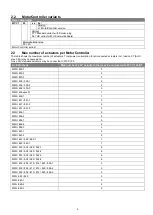
7.1.2 Max. cable length
– ±24V standard actuators
The actuator cable must have 2 wires minimum.
±24V standard actuators
The PE wire/the green-yellow earth wire must not be used
Cable-
cross-section [a]
Total
actuator current [l]
3-wire
0.75mm²
3-wire
1.50 mm²
5-wire
1.50 mm²
2-wire
parallel
3-wire
2.50 mm²
5-wire
2.50 mm²
2-wire
parallel
3-wire
4.00 mm²
1A
42m
84m
168m
140m
280m
224m
2A
21m
42m
84m
70m
140m
112m
3A
14m
28m
56m
47m
93m
75m
8
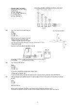
Connection plan for WCC 103
The above connection plan shows a WCC 103 MotorController

