background image

37

4. 

For the Service Technician

Service level

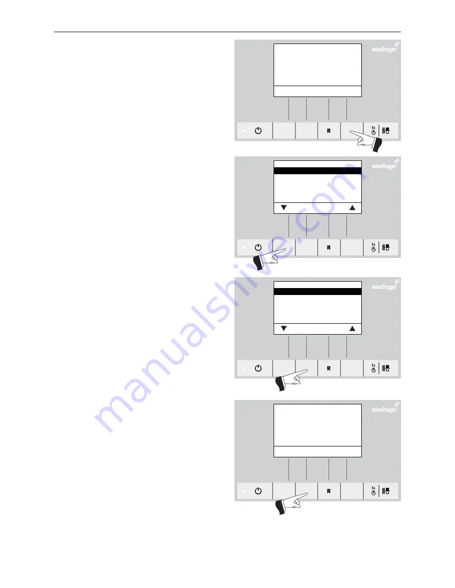
Pressing the 

Menu

 button (Fig. 96) shows the „Opera-

tor level“, „Service level“, „Information level“ and „MES 
Module

1

“ in the display – Fig. 97.

Use the 

arrow 

buttons to select the “Service level” sub-

menu – Fig. 97.

Press and hold the 

Choose

 button for 5 seconds (Fig. 98). 

The display shows „Service level only for trained service 
personnel“ – Fig. 99. 

1 only displayed when an MESplus control is present and this has been adjusted by a trained service technician in the basic settings

Press for 5
seconds

Press for 5
seconds

Fig. 96   

Boiler temperature

(Operating phases)

  Info 


Menu

42

°C

Fig. 97   

Operator level

Service level

Information level
MES Module

1


Choose 

Back 

Fig. 98   

Operator level

Service level

Information level
MES Module

1


Choose 

Back 

Fig. 99   

Service level only
for trained service personnel


5s 


Summary of Contents for BioWIN 2

Page 1: ...PELLETS Assembly instructions BioWIN 2 Pellet central heating boiler Output range 3 to 25 9 kW 07 2014 093403 01 ...

Page 2: ...s of parts for installation 12 2 4 2 Taking into the building and installing 13 2 4 3 Installation observe minimum clearances section 2 4 4 15 2 4 4 Minimum service clearances for fire protection cleaning and maintenance 17 2 4 5 Install the filling and evacuation cock 18 2 4 6 Changing flue connection on the back 19 2 4 7 Mount Reserve supply container L 200 kg 20 2 4 8 Install reserve supply con...

Page 3: ...al data General 49 5 3 Dimensional sketches 50 6 Electric connecting diagrams 52 6 1 Basic BioWIN 2 Exklusiv Premium circuitry 52 6 2 Basic BioWIN 2 Klassik circuitry 53 6 3 BioWIN 2 connecting diagram changeover unit 54 6 4 BioWIN 2 pellet feed connecting diagram with mixer for buried tank 55 6 5 Circuit diagram for BioWIN 2 pellet feed with 1 probe suction solution 55 6 6 Connecting diagram for ...

Page 4: ...ements according to DIN 18160 T1 or other appro priate officially approved may be connected to the hearths The flue gas system must display at least the following classification Temperature class T400 nominal operating temperature 400 C Soot fire resistance class G flue gas system with soot fire resistance Corrosion resistance class 2 suitable for unprocessed wood fuels We would recommend fitting ...

Page 5: ...m combustion and at maximum efficiency The pellets can be stored in bulk in a storage room sheet steel tank fabric tank or a buried tank The requirements for pellet storage are defined in ÖNORM M7137 for Austria or the Firing Ordinance FeuV for Germany See the separate planning documents for planning information about pellet storage Maximum transport length or height for a pellet feed system These...

Page 6: ...om above Fig 4 Storage room Boiler room view from above Furthest away probe changeover unit Storage room Suction turbine BioWIN 2 10 26 kW Boiler room Furthest away probe changeover unit Storage room Suction turbine BioWIN 2 10 26 kW Boiler room BioWIN 2 102 262 3 probe BioWIN 2 102 262 8 probe Information For storage rooms smaller than 2 m without a sloping floor for storage rooms between 2 and 4...

Page 7: ...er installed correctly 2 System fully wired up electrically 3 System rinsed filled and vented heat consumption must be possible 4 Boiler connected to domestic water and filled 5 Sufficient quantity of fuel available pellets split logs oil or gas 6 The customer must be present during start up The initial start up cannot be carried out if any of these points are neglected The customer will be charge...

Page 8: ...Reserve supply container net 28 42 42 28 3 Reserve supply container L 200 kg with wooden shed kg 107 107 Reserve supply container L 200 kg net 81 81 4 Cladding kg 33 5 Auger motor kg 3 5 6 Ash box kg 12 2 For the Installer 2 1 Delivery packaging When delivered the boiler and reserve supply container are covered in a plastic bag and packed inside a stable crate Cladding and installation parts are i...

Page 9: ...valve is always required for the BioWIN 2 in order to protect the boiler and one must be fitted in each heating circuit A feed contact thermostat FK 001 must be installed for underfloor circuits 2 2 4 Circulation pump Since 2013 in Europe new circulation pumps are required to fulfil minimum energy efficiency requirements Ple ase refer to the Energy Efficiency Index EEI 2 2 5 Return temperature The...

Page 10: ...ue interface The controller passes the external boiler temperature setpoint via the analogue 0 10 V interface 2 2 8 Heating water Attention The chemical composition of the heating water must conform with local legislation and meet the directives guidelines and standards e g ÖNORM H 5195 VDI 2035 SWKI BT 102 01 Applicable for Austria excerpt from ÖNORM H 5195 a According to ÖNORM M 5195 2010 editio...

Page 11: ... as follows the flow of air must not be restricted in any way by the weather e g snow leaves the free cross section area remains the same when taking the cover grille discs etc into consideration Applicable for Germany excerpt from the Firing Ordinance September 2007 For hearths with a nominal output of not more than 35 kW in total that are dependent on surrounding air supply of combustion air wil...

Page 12: ...8 Top door hinge 9 Side panel 10 Cladding door 11 Coasting surface insulation 12 InfoWINplus 13 Switch cover 14 Cover 15 Cover for reserve supply container 16 Cover below for reserve supply container below only in BioWIN 2 Klassik Premium 17 Ash box base only BioWIN 2 Exklusiv 18 Ash box only BioWIN 2 Exklusiv Reserve supply container L 200 kg 19 Reserve supply container L 200 kg 20 Leg 21 Cover 2...

Page 13: ...th a hand cart and tension belt see Fig 13 14 2 4 2 1 Remove crate Information The base of the boiler is secured to the floor plate by 2 screws positioned on either side Fig 7 Boiler and reserve supply container in the crate Premium 612 812 1 1 6 1 660 767 6 8 2 1 Fig 7 1015 820 5 1 6 1 Boiler Reserve supply container with without pellet feed Reserve supply container L 200 kg Boiler and reserve su...

Page 14: ...llet and transport it where it is to be installed a by hand Fig 9 12 b with hand cart and tension belt Fig 13 14 c with eyelet and crane not included in scope of delivery Fig 15 16 a by hand Fig 11 Grip position for auger tube and flue outlets Fig 12 Push boiler off pallet Fig 13 Secure boiler to pushcart with tension belt Fig 14 14 Lift the boiler off the pallet with the hand cart ...

Page 15: ...pecial foundation 2 4 3 1 Installation flush to wall top flue connection The boiler can be installed flush to the wall Before installation the rear panel has to be removed You also have to cut into the insulation and seal the supply and return connections Fig 17 Note Care must be taken with regard to wall flush installation to ensure that the piping is sealed com pletely before actually installing...

Page 16: ...sly Hydraulic adapter distributor 1 See separate provided installation instructions for the hydraulic adapter distributor 1 BIO 061 2 4 3 2 2 Installation with wall clearance flue connection at rear see section 2 4 6 Move the boiler into position and use the 4 set screws to align it horizontally or inclined slightly upwards towards the rear To align the boiler place the spirit level on top of the ...

Page 17: ...ance The following minimum service clearances from flammable materials and for connections cleaning and mainte nance must be complied with Attention Follow the installation guidelines for boiler rooms The configuration of the exhaust line must com ply with technical fire protection requirements in accordance with the applicable regulations stan dards and guidelines 1075 min 30 min 30 710 BW 102 15...

Page 18: ... view from above Flue connection rear 2 4 5 Install the filling and evacuation cock Remove handle from filling and evacuation cock Fig 24 Screw the filling and evacuation cock into the base of the boiler on the left hand side The handle must be po sitioned on the right Re attach the handle Fig 25 Fig 24 Tighten the handle of the filling and evacuation cock Fig 25 Screw the filling and evacuation c...

Page 19: ... surfaces cover Fig 26 Unscrew the screws on the cover and remove the screws Fig 27 28 Punch out the cut out on the back panel Fig 29 Remove insulation from all around the flue gas blower Fig 30 Cut open the cable ties around the blower cable Fig 31 Fig 26 Remove insulation Fig 27 Remove screws Fig 28 Remove the cover Fig 29 Punch out the cut out Fig 30 Remove insulation from the flue gas blower F...

Page 20: ...Re screw the flue gas blower into place adjusted by 90 see Fig 33 Insert insulation included on side at base of flue gas blower at the top behind the flue outlet Fig 34 Fig 32 Remove 4 screws Fig 33 Re screw the flue gas blower into place adjusted by 90 Fig 34 Position insulation included on side at base of flue gas blower 2 4 7 Mount reserve supply container L 200 kg See separate assembly instruc...

Page 21: ... side Fig 37 and push the cover down to take it off completely it is attached with a bayonet catch Fig 38 Screw the base of the reserve supply container to the auger tube with M8 x 16 hexagon screws provided at tached to reserve supply container in a plastic bag Fig 39 Fig 36 Insert the auger into the auger tube Fig 37 Suspend reserve supply container from 2 hooks marked Fig 38 Tighten fastenings ...

Page 22: ...the auger Fig 45 Plug in the auger motor plug and the proximity switch plug Fig 46 Reattach the cover to the reserve supply container and secure with 2 self tapping screws Fig 47 Fig 42 Insert sensor for safety thermostat auger tube as far as they go 1 Fig 43 Hook in the auger motor 2 Fig 44 Screw the auger motor into position Centring screw Lug 2 x M8x16 3 Fig 45 Mount gear 1 x M6x12 Fig 46 Conne...

Page 23: ...t of cover from the control panel and pull out the cable plus grommet from the Info WIN Raise the cover push it backwards and remove it Fig 49 Connect the provided plug with bridge to the PCB X22 3 pin and to the suction turbine power plug 6 pin Fig 51 mains power plug suction turbine 2 4 9 Reserve supply container cladding Hook cladding at rear left into the bayonet locks Fig 52 53 Fig 49 Remove ...

Page 24: ...ch out Punch out cladding flue connection at top Do not punch out cladding flue connection at rear Information Carefully insert the cladding top left to ensure that the reserve supply container is not scratched at the front Fig 55 Carefully insert the cladding top left lay the mains power plug suction turbine cable into the notch and secu re cladding with 6 self tapping screws Fig 56 Hook cladding...

Page 25: ...nge loose at top as it should be allowed to move and hold in place with 2 self tapping screws Fig 60 Hook side panel into the 4 bayonet locks Fig 61 62 Fig 63 Fitting cladding door at top and bottom Fig 64 Tighten the top door hinge and screw the side panel into place with 2 self tapping screws 3 x Hook the top and bottom of the cladding door into the hinges Fig 63 and tighten the top door hinge F...

Page 26: ...ig 68 2 4 12 Cladding cover If the flue connection is at the top punch out the cut out on the cladding cover Fig 69 If the flue connection is at the rear do not punch out Punch out cladding cover flue connection at top Do not punch out cladding cover flue connection at rear Place the cladding cover on the boiler Fig 70 Fig 65 Mount the control panel cover fitting insulation at rear Fig 66 Screw In...

Page 27: ...he base for the ash box underneath the reserve supply container and bend the front part down to the gro Fig 71 Push the ash box in at a slight left angle and push in the ash box handle leaving the openings on the side of the ash box open Fig 72 Close the bracket fastener Fig 73 Adjust the ash box set screw BioWIN 2 Exklusiv only on the boiler Fig 74 Note The floor underneath the ash box has to be ...

Page 28: ... the flexible earth leads on all hose ends and bend inwards into the hose Fig 76 Important Also refer to assembly instructions for supply and return air hose in enclosed manual for storage room accessories changeover unit Remove the 4 screws for the reserve supply container lid and take off the lid Fig 77 Attach the fastening clips to the hoses and connect Fig 77 Note If you have problems connecti...

Page 29: ...sory for BioWIN 2 Premium Exklusiv only 6 Folders containing instructions 1 2 3 4 5 Fig 78 Cleaning and operating implements Fig 79 Cleaning brush and spatula on inside of cladding door Fig 80 Allen key and folder with instruction underneath cover 1 2 3 6 1 pellet pile for bridging purposes or when manually filling the reserve supply container if feed is not complete ...

Page 30: ...nd of stainless steel flue accessory fits exactly onto flue outlet in BioWIN 2 so that any condensation flowing back cannot leak out of the exhaust pipe The parts must be secured with pipe clamps to ensure adequate leaktightness and stability Pipelines are not allowed to sag h The entire exhaust line has to be insulated to a thickness of at least 2 cm i The entire exhaust line has to be able to be...

Page 31: ...st connection at rear view from front drawing does not show exhaust pipe insulation 2 1 1 3 Fig 82 Exhaust connection at top view from front drawing does not show exhaust pipe insulation 1 1 4 3 Fig 83 Exhaust connection at rear view from top drawing does not show exhaust pipe insulation 4 3 Fig 84 Exhaust connection at top view from top drawing does not show exhaust pipe insulation ...

Page 32: ...ble is longer than 5 m Cable for changeover unit motor low voltage 4 x 1 5 mm2 The boiler is pre wired and internally fused with a T 6 3 A fine wire fuse to protect against short circuit By special order up to 3 MESplus modules including boiler sensor will be installed in the control panel and wired at the factory Fig 85 if there are more than 3 modules they are installed in the wall mount casing ...

Page 33: ...over by raising it Remove insulation from the coasting surfaces cover Fig 89 Remove the control panel cover by unscrewing 3 screws from front and pull out the InfoWIN cable and grom met Push the cover backwards and remove it Fig 90 Fig 86 Remove the cladding cover Fig 87 Loosen the 2 screws on the switch cover Fig 88 Disconnect the InfoWIN cable and remove the switch cover Fig 89 Remove insulation...

Page 34: ...the separate wiring of the extra low voltage line sensor and low voltage line 230 V AC Fig 92 The terminal block connection screwless cage spring type terminals is executed with a fine wire PVC sheathed cables Fig 92 The cables can be laid from the top bottom right and rear through the pre punched feed throughs Fig 93 Connection diagrams for the control are enclosed for more connection diagrams se...

Page 35: ...nd repair work Service and repair may be performed only by appropriately qualified technicians Please note Disconnect the mains power plug before opening the control panel for service or repair purposes Remove the cladding cover Fig 94 followed by the insulation covering the coasting surface cover Disconnect the mains power plug Fig 95 Attention After the emergency shut off switch trips the boiler...

Page 36: ...file Cleaning interval correction Input X14 5 Limits for blower speed Minimum operating time with buffer Full service Flue gas min temperature Parameters Operator level Settings on the operator level see BioWIN 2 Operating Manual Service level Reserved for trained service personnel only Information level see BioWIN 2 Operating Manual MES Module1 see separate instructions for InfoWINplus Master ope...

Page 37: ...shows Service level only for trained service personnel Fig 99 1 only displayed when an MESplus control is present and this has been adjusted by a trained service technician in the basic settings Press for 5 seconds Press for 5 seconds Fig 96 Boiler temperature Operating phases Info Menu 42 C Fig 97 Operator level Service level Information level MES Module1 Choose Back Fig 98 Operator level Service...

Page 38: ...ted with the arrow buttons then confirmed using the Choose button Fuel quantity auger conveyor Delivery time ignition phase Hysteresis Burner ON Maximum value offset temperature Set temperature ext heating requirement Type of pellet feed system Operating time of suction turbine Ash removal profile Cleaning interval correction Input X14 5 Limits for blower speed Minimum operating time with buffer F...

Page 39: ...e Actual value 75 C min 60 C max 85 C Save Back Maximum value offset temperature This is the maximum setpoint achievable in normal heating operation Factory setting 75 C Setting range 60 85 C Fig 106 Set temperature ext heating requirement Actual value 70 C min 35 C max 85 C Save Back Set temperature ext heating requirement This is the set temperature for external heating requirement Factory setti...

Page 40: ...oval profile Stage 0 Stage 1 Stage 2 Stage 3 Save Back Information Restore factory setting for next delivery of pellets Stage 0 to Stage 3 very low proportion of ash very high proportion of ash possibly formation of slag Cleaning interval correction The cleaning interval is basically dependent on the proportion of ash in the pel lets and the ash removal profile This adjuster can be used to extend ...

Page 41: ...2 Minimum Maximum Minimum Maximum Factory setting rpm 900 2300 1050 2700 Setting range rpm 900 1300 2300 2700 1050 1450 2700 2700 Minimum operating time with buffer This function is not yet available Fig 113 Air intake flap Operating time 300 sec min 30 sec max 600 sec Save Back Fig 114 Limits for blower speed Minimum 600 rpm Maximum 1450 rpm Choose Back Fig 115 Minimum operating time with buffer ...

Page 42: ... Choose button The actuators are switched off again after 1 minute A self test is started at the end of an actuator test Fig 119 Induced draught fan Auger conveyor Ash removal Ignition element Ash conveyor Heating surf cleaning Choose Back Induced draught fan Auger conveyor Ash removal Ignition element Ash conveyor Heating surface cleaning Suction turbine Probe switching Output X24 Fig 120 Suction...

Page 43: ...InfoWINplus can show the display texts in various languages The language required can be selected in this sub menu Fig 126 Temperature format C F Save Back Temperature format All temperatures are displayed in the chosen format e g 30 6 C or 87 0 F Factory setting C Selection C and F Fig 127 Time format 24h 12h Save Back Time format The time is displayed in the chosen format e g 14 12 or 02 12 PM F...

Page 44: ...ou can change the name e g BioWIN 2 of the boiler Fig 130 Function BioWIN 2 Save Back 4 3 5 Installation of MESplus modules Display if an MESplus module is installed connected or uninstalled disconnected Fig 131 Installation procedure active Animated symbol ...

Page 45: ...tings are available in the basic settings Language selection Boiler MB SMS ELG Ethernet Update Software Update Firmware Display contrast The basic settings are used to set whether the InfoWINplus controls a wood or pellet boiler or whether it is solely used as master operation switch the master operation functions on and off activate deactivate remote switching by text message The basic settings a...

Page 46: ...the order Selection yes with MESplus system control no no MESplus system control Fig 138 SMS Yes No Save Back SMS Setting to define whether remote switching by text message is possible Factory setting is set in the factory before delivery as per the order Selection yes with remote switching no no remote switching Fig 135 Language selection Deutsch English Française Italiano Dansk Save Back Languag...

Page 47: ...rface is being started Fig 142 Update Firmware start Back Update Firmware The update procedure to update the LON Controller firmware is being started The LON Controller firmware is included in the InfoWINplus software therefore no external update tool is required Fig 143 Display contrast Correction 5 Back Display contrast Adjusters to set the contrast of the display Factory setting 5 Setting range...

Page 48: ...0044 0 0118 0 0049 0 0146 Flue gas temperature rated load1 TW C 73 98 77 119 82 127 85 134 Necessary feed pressure PW Pa 0 5 0 5 0 5 0 5 Flue gas connection diameter Ø mm 130 130 130 130 Note Connection pipe to flue must have at least 2 cm of thermal insulation In marginal cases external combustion air intake can be conducted with a tested wind protection fixture of type FC 52x 5 Technical data 5 ...

Page 49: ...Klassik Exklusiv S Klassik L Exklusiv SL Premium Exklusiv 107 200 max 71 Overall weight net kg Klassik Klassik L Premium Exklusiv Exklusiv S Exklusiv SL 247 300 261 286 272 325 269 322 283 308 295 348 Dimensions W x D x H mm Klassik Exklusiv S Premium Exklusiv Klassik L Exklusiv SL 1075 x 710 x 1453 1075 x 710 x 1705 1422 x 710 x 1470 1075 x 780 x 1453 1075 x 780 x 1705 1422 x 780 x 1470 For furth...

Page 50: ... Exklusiv S Klassik Rear view KV Boiler feed 1 tube KR Boiler return 1 tube E Discharge A Pellet feed 50 mm Ø pipe B Reverse air flow 50 mm Ø pipe KT Boiler temperature sensor AO flue connection top Ø 130 mm AH flue connection rear Ø 130 mm EA Electrical connections Z External combustion air Ø 100 mm 1075 710 BW 102 152 780 BW 212 262 562 130 79 96 AO KT E AH Fig 145 BioWIN 2 Exklusiv Premium Exkl...

Page 51: ...KV Boiler feed 1 tube KR Boiler return 1 tube E Discharge A Pellet feed 50 mm Ø pipe B Reverse air flow 50 mm Ø pipe KT Boiler temperature sensor AO flue connection top Ø 130 mm AH flue connection rear Ø 130 mm EA Electrical connections Z External combustion air Ø 100 mm 1422 562 130 79 96 AO KT E AH 710 BW 102 152 780 BW 212 262 Fig 147 BioWIN 2 Exklusiv SL Klassik L view from above ...

Page 52: ...ellow orange red brown 1 2 3 1 2 4 B7 1 safety temperature limiter boiler 100 C 1 N 2 N 3 L 4 L optional accessories XA boiler sensor V4 1 pellet feed A2 A1 K2 12 11 5 4 X1 X17 X22 X21 X16 X15 X14 X13 X18 X12 X11 X10 X2 X19 X20 X5 X6 X24 X7 X3 X4 X8 X9 2 2 1 1 4 3 2 1 2 1 3 2 1 6 5 4 3 2 1 2 1 2 1 3 2 1 3 2 1 Lon Lon GND 12V GND Lon Lon 12V 1 2 3 1 2 1 2 3 4 1 2 3 1 2 3 4 1 2 1 2 3 4 5 6 1 2 3 1 2...

Page 53: ...nsor V4 1 5 4 brown blue black Näherungsschalter Deckel P9 1 X1 X17 X22 X21 X16 X15 X14 X13 X18 X12 X11 X10 X2 X19 X20 X5 X6 X24 X7 X3 X4 X8 X9 2 2 1 1 4 3 2 1 2 1 3 2 1 6 5 4 3 2 1 2 1 2 1 3 2 1 3 2 1 Lon Lon GND 12V GND Lon Lon 12V 1 2 3 1 2 1 2 3 4 1 2 3 1 2 3 4 1 2 1 2 3 4 5 6 1 2 3 1 2 3 1 2 1 2 3 4 EDV NR 011990 L N PE L N LL N PE RL L L L N PE L N PE N PE N L L N PE L L L L N PE L L N PE LO...

Page 54: ...han 5 m Cable for changeover unit motor low voltage 4 x 1 5 mm2 094546 00 X1 X17 X22 X21 X16 X15 X14 X13 X18 X12 X11 X10 X2 X19 X20 X5 X6 X24 X7 X3 X4 X8 X9 2 2 1 1 4 3 2 1 2 1 3 2 1 6 5 4 3 2 1 2 1 2 1 3 2 1 3 2 1 Lon Lon GND 12V GND Lon Lon 12V 1 2 3 1 2 1 2 3 4 1 2 3 1 2 3 4 1 2 1 2 3 4 5 6 1 2 3 1 2 3 1 2 1 2 3 4 011990 EDV Nr FA BioWIN 2 M PE LL RL N PE M9 1 1 3 2 S Higt Voltage 230 VAC Extra...

Page 55: ...ioWIN 2 M PE L2 N PE L1 M11 1 094543 00 6 4 BioWIN 2 pellet feed connecting diagram with mixer for buried tank Operation with a mixer must be set on the service level see section 4 3 1 Parame ters type of pellet feed system 094545 00 A2 A1 K2 M PE L2 N PE L1 M PE L N PE PE PE 04 03 14 13 24 23 X1 X17 X22 X21 X16 X15 X14 X13 X18 X12 X11 X10 X2 X19 X20 X5 X6 X24 X7 X3 X4 X8 X9 2 2 1 1 4 3 2 1 2 1 3 ...

Page 56: ... X3 X4 X8 4 3 2 1 2 1 3 2 1 6 5 4 3 2 1 2 1 1 2 1 2 3 4 5 6 1 2 3 1 2 3 1 2 L N PE N L L N PE L L L L N PE K50 20min Kx 04 03 M N L A2 B1 A1 15 18 16 6 L 4 L 5 L 3 N 1 N 2 N XS X15 X14 X13 X18 X12 X24 X7 X3 X4 X8 4 3 2 1 2 1 3 2 1 6 5 4 3 2 1 2 1 1 2 1 2 3 4 5 6 1 2 3 1 2 3 1 2 L N PE N L L N PE L L L L N PE K50 20min EDV Nr 011990 EDV Nr 011990 M11 1 M11 1 Air intake flap with limit switch Air in...

Page 57: ...6 X24 X7 X3 X4 X8 X16 X12 4 3 2 1 2 1 3 2 1 6 5 4 3 2 1 2 1 1 2 1 2 3 4 5 6 1 2 3 1 2 3 1 2 L N 1 2 4 3 1 2 FA BioWIN 2 X6 1 2 4 B7 1 094682 00 6 7 Connecting diagram for flue gas thermostat Operation with a flue gas thermostat must be set on the service level see section 4 3 1 Parameters Input X14 5 V15 1 X15 X14 X13 X18 X12 X24 X7 X3 X4 X8 4 3 2 1 2 1 3 2 1 6 5 4 3 2 1 2 1 1 2 1 2 3 4 5 6 1 2 3 ...

Page 58: ...1 4 3 2 1 2 1 3 2 1 6 5 4 3 2 1 2 1 2 1 3 2 1 3 2 1 Lon Lon GND 12V GND Lon Lon 12V 1 2 3 1 2 1 2 3 4 1 2 3 1 2 3 4 1 2 1 2 3 4 5 6 1 2 3 1 2 3 1 2 1 2 3 4 EDV NR 011990 L N PE L N LL N PE RL L L L N PE L N PE N PE N L L N PE L L L L N PE L L N PE LON FA BioWIN 2 GND 12V GND GND GND GND GND 12V I O GND GND GND GND GND P9 1 1 2 3 094770 00 P9 1 Proximity switch cover 1 Black 2 Blue 3 Brown ...

Page 59: ...arranty requires that the boiler and related accessories be properly installed and started by Windhager Customer Service or Customer Service Partner otherwise the manufacturer s warranty will not be honored Malfunctions resulting from improper operation or adjustment as well as use of poor or not recommended fuel types are not covered by the warranty Further the warranty shall be void if equipment...

Reviews: