41
1
+5VSB
2
+5VSB
3
Data -
4
Data +
5
Ground
6
Ground
* Res(J10) with P-CAP(J14) select one
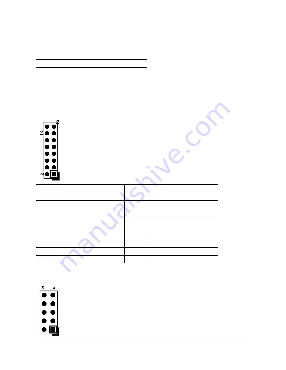
J15
–TPM / ID-394
Pin
#
Signal
Description
Pin #
Signal
Description
16
+3.3VSB
15
SUS_STAT#
14
SMB DATA
13
GND
12
SMB CLK
11
Debug CLK
10
CLKRUN#
9
LPC Frame#
8
+5VSB
7
LPC AD3
6
+3.3VS
5
LPC AD2
4
SERIRQ
3
LPC AD1
2
PLT reset#
1
LPC AD0
J16
– For JTAG
Summary of Contents for WLP-7B20 Series
Page 15: ...6 System View WLP 7B20 10 Outline Drawing Panel Mount WLP 7B20 12 Outline Drawing Panel Mount...
Page 16: ...7 WLP 7B20 15 Outline Drawing Panel Mount...
Page 17: ...8 I O connectors Note Share the same place with DVI output DVI and VGA not simultaneously...
Page 27: ...18...
Page 36: ...27 parameters...
Page 43: ......


