background image

13

OPM-160/A

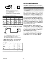
For additional information on wire sizing refer to table 310-

16 of the National Electrical Code ANSI/NFPA 70.

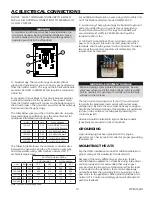
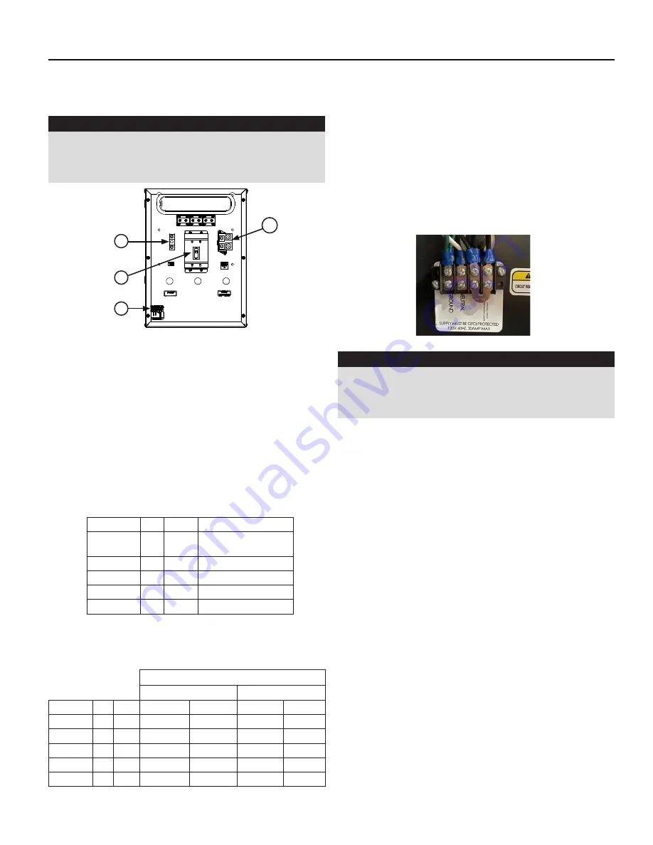
C - Ground Lug, These ground lugs are bonded to ground 

and are provided for you to connect your ground wire 

from the transfer switch to. The lugs on the 60kW will 

accommodate #1 AWG to 250 MCM and should be 

torqued to 250 in. lbs. 

D. 120 Volt Terminal Block. These terminals are for shore 

power. For a power line with one lead, plug into either 

terminals, ensuring the jumper is still connected. To isolate 

two leads for use of two separate circuit breakers, the 

jumper must be removed.

WARNING: EQUIPMENT DAMAGE

When installing a three-phase 240 Volt system, be sure 

you know which lead is the high voltage “wild” leg (208 

Volt to neutral). The generator normally carries the high 

voltage on the G2 lead.

The load current carrying wires (L) and (T) must be sized 

to handle the maximum load current without excessive 

voltage drop. By code, the wire must be heavy enough to 

handle the full current rating of the mainline circuit breaker 

(or fuse) in the entrance (or sub-panel) protecting the 

contactor switch.

All wires should be installed in rigid or flexible conduit. 

(knockouts are provided in the control box).

GROUNDING

A grounding lug has been provided on the engine 

generator set. Check your local codes for proper grounding 

requirements.

MOUNTING THE ATS

See the ASCO installation manual for additional details on 

proper wiring of the Automatic Transfer Switch.

Because of the many different types of service, feeder, 

and distribution equipment, no specific wiring instructions 

can be provided. It is recommended that only copper 

wire be used. In all cases it is essential that while the load 

is connected to the generator, there can be absolutely 

no feedback from the generator to the power line or the 

power line to the generator. When properly installed, the 

normal A.T.S. Control and safety systems will eliminate all 

paths for feedback.

NOTICE:  CLASS 1 WIRING METHODS ARE TO BE USED 

FOR ALL FIELD WIRING CONNECTIONS TO TERMINAL OF 

A CLASS 2 CIRCUIT.

WARNING

A mainline circuit breaker has been provided inside the 

generator housing. During all wiring installation, make 

sure the breaker is in the off position and the generator 

operators switch is in the off position. 

A - Neutral Lugs, These neutral lugs are isolated from 

ground and provided for you to connect your neutral wire 

from the transfer switch. The lugs on the 60 kW will handle 

wire sizes #4 AWG to 300 MCM and should be torqued to 

250 in lbs. 

B - Generator Circuit Breaker, This circuit breaker provides 

overload protection for the generator. Your power feeds 

from the transfer switch will connect to the bottom lugs on 

the circuit breaker. The generator power feeds have already 

been wired into the upper lugs.

The table below gives you the circuit breaker size, lug wire 

sizes and torque specification. (see the actual breaker for 

additional information and restrictions)

Volts

PH

Amp

Wire Capability

120/240

1

250

(1) #1 AWG-600 kcmil or

(2) #1 AWG-250 kcmil

120/208

3

225

(1) 4 AWG-300 kcmil

120/240

3

225

(1) 4 AWG-300 kcmil

277/480

3

100

(1) #14 - #3/0 AWG

346/600

3

80

(1) #14 - #3/0 AWG

The following table shows the minimum conductor sizes 

between the generator and the ATS, based on wire type 

and temperature rating. Wire has been derated 40° C 

ambient temperatures.

Wire Temperature Rating

Cu Conductor

Al Conductor

Volts

PH Amp

75°C

90°C

75°C

90°C

120/240

1

250

300

4/0

500

350

120/208

3

225

250

4/0

400

300

120/240

3

225

250

4/0

400

300

277/480

3

100

2

3

1/0

1

346/600

3

80

3

4

2

3

Note - Two 250 MCM may be used.

AC ELECTRICAL CONNECTIONS

 A


C


B


D

Summary of Contents for PSS60F4 Series

Page 1: ...need to contact us on this unit it will help us to respond to your needs faster MODEL __________________________________________________ SERIAL NUMBER _________________________________________ PURCHAS...

Page 2: ...AL GAS NG FUEL PRESSURE NG LP FUEL CONVERSION INSTALLING THE BATTERY 11 SERVICING BATTERIES BATTERY CHARGING BATTERY CHARGER BLOCK HEATER GROUNDING MOUNTING THE ATS AC ELECTRICAL CONNECTIONS 13 DC ELE...

Page 3: ...CO generator You have selected a high quality precision engineered generator designed and tested to give you years of satisfactory service To get the best performance from your new generator it is imp...

Page 4: ...cause cancer birth defects or other reproductive harm and developmental issues For more information go to www P65Warning ca gov C Do not smoke or use open flame near the generator set or fuel tank D K...

Page 5: ...60 60 60 Engine Model Ford 6 2L Starting System 12 Volt Muffler Standard Fuel Consumption LP NG Full Load 8 2 Gal Hr 750 685 BTU Hr 760 Ft Hr 797 416 BTU Hr Generator Testing Resistance Note Review th...

Page 6: ...nt The ATS also contains the power failure sensing circuitry necessary to start and stop the engine generator set The transfer switch is also equipped standard with a 3 second start delay and a 15 sec...

Page 7: ...ceived is the correct model and review the specification pages in this manual to ensure that this unit meets your job requirements CAUTION EQUIPMENT DAMAGE These units are shipped with oil and a 50 50...

Page 8: ...rue for the single low pressure regulator it should also be a minimum of 10 feet from the unit If this is not done the demand regulator on the unit and the pressure regulator in the fuel line will int...

Page 9: ...Up to 25 ft pipe 25 100 ft 1 pipe Over 100 ft Use a two regulator system Allow an additional 3 feet for each standard elbow DO NOT use street ells restrictive LP TANK SIZING Tank size is based off of...

Page 10: ...the oil level in the crankcase If it is low refill to the full mark with the proper weight grade of oil as recommended by the engine manufacturer s maintenance instructions The necessity of using the...

Page 11: ...tery terminal is connected to the negative cable ground from the engine generator assembly All connections must be clean and tight Check the electrolyte fluid in the battery periodically to be sure it...

Page 12: ...ational Electric Code It is suggested that this circuit be fused to 20 Amps Low Charge Mode The illuminated blue power LED and red low charging LED This indicates the Low Charge mode is in process Whe...

Page 13: ...connected to the generator there can be absolutely no feedback from the generator to the power line or the power line to the generator When properly installed the normal A T S Control and safety syst...

Page 14: ...ice disconnect must be installed in front of the ATS panel as the ATS is not service entrance rated This will allow you to test the generator under load Should you ever have to work on the switch you...

Page 15: ...charger to DSE7310 MKII controller D Remote Display Panel Interface Terminals These interface terminals are pre wired to allow for the connection of a remote display This display allows for the remot...

Page 16: ...r WINCO Service Department for your warranty to become valid After completing the checklist the engine generator set is ready for initial start up WARNING EQUIPMENT DAMAGE Before attempting to start t...

Page 17: ...it is in the manual mode Pressing the STOP RESET button will stop the unit immediately Pressing the AUTO mode button will stop the unit but only after the cool down timers have timed out and there is...

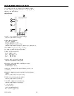
Page 18: ...dampening effect 4 LINK POWER RESPONSE A B 550kW Fast B C 100 550kW Fast A C 100kW Fast B D 100kW Slow 5 UFRO Under Frequency Roll Off Clockwise decreases KNEE point 6 SWITCH Select alternator frequen...

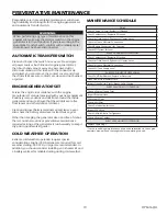
Page 19: ...or preventative maintenance required as long as the generator is run bi weekly to keep it dry and in good working order COLD WEATHER OPERATION Extreme cold weather operation requires special considera...

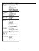
Page 20: ...Governor is defective ENGINE CRANKS BUT WILL NOT START 1 Improper fuel pressure being delivered to unit 2 Fuel supply shut off 3 Fuel supply empty 4 Defective spark plug 5 Defective engine ignition mo...

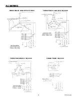
Page 21: ...8 165 HIGH AND LOW WYE THREE PHASE LOW WYE 120 208 VOLTS THREE PHASE HIGH WYE 277 480 VOLTS THREE PHASE HIGH WYE 277 480V THREE PHASE LOW WYE 120 208V THREE PHASE DELTA 120 240 VOLTS THREE PHASE AC WI...

Page 22: ...8 1 1 8 8 62 12 6 67 57 200 1 8 6 7 1 7 21 1 2 1 1 1 51 66 8 211 725 5 9 6 216 5 9 51 6 5 37 21 7 33 3 1 3 57 6 0 3 6 7 1 335 7 7 1 1 51 66 366 25 7 7 7 5 1 02 3 57 096 7 6 5 1 217 16 35235 7 5 1 250...

Page 23: ...57 1 1 77 77 1 5 7 50 1 2 6 211 725 211 725 66 86 86 86 86 86 36 1 2 8 1387 20021 6 5 1 1 6 5 1 1 1 1 1 36 32 5 6 7 66 0 5 1 6723 6 7 66 8 6 7 21 6 7 9 5 92 7 8670 17 5 267 7 9 5 1 855 17 66 7 50 1 2...

Page 24: ...omponent of the product that is no longer manufactured or available Additionally WINCO Inc will not be liable for any engine replacement that may require an emissions tier level change THERE ARE NO EX...

Reviews: