background image

ENTERPRISE 

A8000


IN-BUILDING CELL SIGNAL AMPLIFIER

33

If you need to view or modify the local amplifier configuration settings, this utility was 
created to help you. With this utility, you can change Cloud Communication Preferences 
and Ethernet settings, as well as enable/disable bands and ports. It can also be used to 
view live band details and the static information such as firmware version.

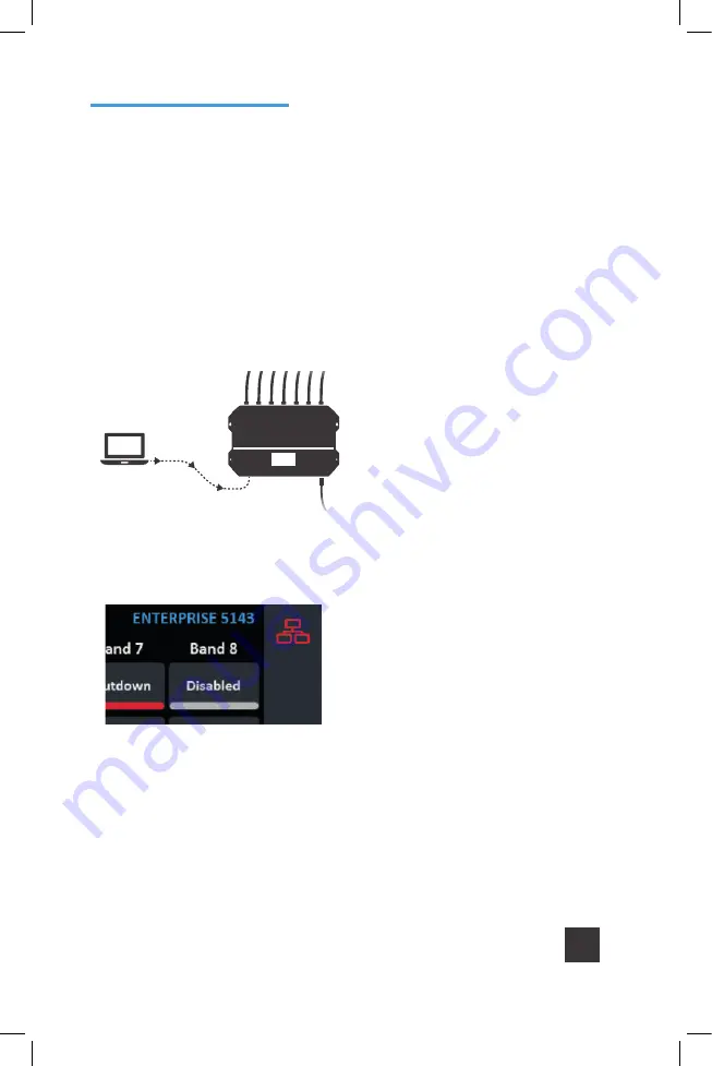
Cat 5/6 cable

To use the Local Amplifier 
Configuration Utility, a laptop 
computer must be connected to 
the 

A8000

 via a Cat 5/6 cable to 

the Ethernet port on the amplifier.

After connecting to the network or 
a laptop, the network icon on the 
amplifier will change color from red to 
yellow. It could take up to two minutes. 

Local Amplifier 

Configuration Utility

Summary of Contents for WilsonPro ENTERPRISE A8000

Page 1: ...A Wilson Electronics Brand Zienihn ahb XeҶ iҶuX Installation Guide ENTERPRISE In Building Cell Signal Amplifier with Multi Tower Targeting MTT Technology ...

Page 2: ...In Building Cellular Connectivity Amplified Commercial grade solutions for improving cell signal coverage ...

Page 3: ...8 33 40 41 42 Index Package Contents About The Enterprise A8000 Additional Features Installation Diagram Menu System WilsonPro Cloud Local Amplifier Configuration Utility Safety Guidelines Specifications Warranty ...

Page 4: ...ENTERPRISE A8000 IN BUILDING CELL SIGNAL AMPLIFIER 1 Enterprise A8000 Amplifier Type G Power Cable E F Power Cable Enterprise A8000 Package Contents ...

Page 5: ...rent bands resulting in improved indoor coverage Covers E UTRA Cell Bands 1 3 7 8 High max downlink power up to 25 dBm EIRP and greater than 100 000 sq ft coverage with a strong 5 bar outside signal Remote system monitoring Connects to WilsonPro Cloud service via Ethernet interface Enterprise A8000 In Building Cell Signal Amplifier System ...

Page 6: ...ud provides ultra high system reliability and guaranteed uptime The Enterprise A8000 amplifier connects to the WilsonPro Cloud right out of the box via a standard Ethernet port The Enterprise A8000 cell signal amplifier systems also incorporate Wilson Electronics state of the art XDR eXtended Dynamic Range technology that prevents signal overload conditions which can in accordance with regulations...

Page 7: ...r Better Control The amplifier is automatically controlled with built in onboard software ensuring reliable connectivity throughout large spaces and multi story buildings The amplifier will adjust its gain level up or down as required by the conditions of the immediate signal environment Color LCD Touch Screen The Enterprise A8000 systems utilize a color LCD touch screen for assessing amplifier pe...

Page 8: ...or an installation in which cell towers for different bands are located in the same direction Outside Antennas 900 2700 MHz Cell Tower Inside Antenna Amplifier Inside Antenna Inside Antenna Inside Antenna Common Note The Enterprise A8000 is configured to common mode by default Installation Diagram The Enterprise A8000 supports up to four inside antennas and are capable of operating in traditional ...

Page 9: ...which cell towers for different bands are located in different directions Outdoor directional antennas can be pointed to provide maximum cell coverage for each band Inside Antenna Outside Antennas 2500 2700 MHz Cell Tower 900 MHz Cell Tower 1700 2200 MHz Cell Tower Inside Antenna Amplifier Inside Antenna Inside Antenna Split Mode ...

Page 10: ...e consumer s responsibility to ensure that structural engineering requirements for potential seismic activity are met per your local requirements This may require wall reinforcement Do not install near sources of high heat or steam or where condensation is likely to occur such as near air conditioners Inspect mounting location conditions to ensure proper wall thickness and no signs of moisture or ...

Page 11: ...pply scan the QR code for quick registration The fuse mark on the switch indicates the fuse holders behind the switch The red orange frame shows the outline of the removable unit With a simple tool the fuse holder unit 1 can be removed from the filter On the topside 2 behind the switch there are two fuse holders for each live connection For fuse replacement replace each with a 5x20mm 0 5A 250V tim...

Page 12: ...d then reboot turn the unit off on the Enterprise A8000 system to reactivate the band and maximize performance When adequate separation is achieved the yellow lights will return to green upon reboot Note when the light is yellow the band is operational however performance is reduced Home Screen Start Up Screen Band Menu Color Description Menu System The Enterprise A8000 takes about 8 seconds to bo...

Page 13: ...Reposition antennas increase separation between indoor and outdoor antennas and point in opposite directions and then reboot turn the unit off on the Enterprise A8000 system to reactivate the band and maximize performance When adequate separation is achieved the red light s will return to green upon reboot Gray indicates band has been disabled MENU SYSTEM cont ...

Page 14: ...ens represented by tabs Tap the tab heading to view each Settings Screen General settings below Note Bands and Ports are disabled or enabled from the Local Amplifier Configuration Utility only Tap Settings Icon in the lower right corner to view the Settings Screen Settings Screen ...

Page 15: ...IN BUILDING CELL SIGNAL AMPLIFIER ENTERPRISE A8000 12 Ethernet Settings Tab Cloud Communication Settings Tab MENU SYSTEM SETTINGS SCREEN cont ...

Page 16: ...ttings Tab Common Mode is configured from the Local Amplifier Configuration Utility and should be set when using a single Outside Antenna Note The Reset Local Comm button resets the login credentials for the Local Amplifier Configuration Utility to factory defaults MENU SYSTEM SETTINGS SCREEN cont ...

Page 17: ...ion Split Mode is configured from the Local Amplifier Configuration Utility and should be set when using separate Outside Antennas for Band 1 Band 3 Band 7 and Band 8 To go back to the Home Screen tap on the Home Icon in the lower right corner MENU SYSTEM SETTINGS SCREEN cont ...

Page 18: ...AL AMPLIFIER 15 To view specific band information such as the strength of the received uplink down link signal outside signal strength and amplifier gain status tap the desired band on the home screen Oscillation Example Band Status Screens ...

Page 19: ...IN BUILDING CELL SIGNAL AMPLIFIER ENTERPRISE A8000 16 Shutdown Example MENU SYSTEM BAND SATUS SCREENS cont ...

Page 20: ...PRISE A8000 IN BUILDING CELL SIGNAL AMPLIFIER 17 The two icons in the upper right provide status related to the Ethernet connection and USB device if inserted Ethernet Status Icon Connectivity Status Screens ...

Page 21: ...onnection Logging into the WilsonPro Cloud via Ethernet If you don t already have a WilsonPro Cloud account at cloud wilsonpro com call 011 749 3085 Monday Friday 8am 5pm so that your account can be created Once your account is set up you can then add multiple customers locations and amplifiers Your supported amplifiers can be added and managed via our WilsonPro Cloud website located at https clou...

Page 22: ... have not been acknowledged After an alert is acknowledged it is no longer included in this chart Total Amplifier Status represents the current near real time status of all amplifiers associated with your account Customer Dashboard WILSONPRO CLOUD cont Adding a Customer To create a new customer from the Dashboard screen click on NEW CUSTOMER NOTE If you don t already have a WilsonPro Cloud account...

Page 23: ... will appear on the dashboard page below the alert and status summary with a default location Primary Secondary Contact A point of contact for the Customer These fields in this section are required Monitor Individual s assigned to track performance of amplifier s See next section if a Monitor has not been created Customer Information This section is pertaining to the business organization utilizin...

Page 24: ...or has not been created click on NEW MONITOR at the top of the webpage Installer Integrator can assign Monitors to track the performance of the amplifier s A Monitor can be made Administrator who can see all information within the account and create additional Monitors Enter information and click SUBMIT ...

Page 25: ...IN BUILDING CELL SIGNAL AMPLIFIER ENTERPRISE A8000 22 WILSONPRO CLOUD cont Creating an Additional Customer Location To create an additional customer location click VIEW Then click ADD NEW LOCATION ...

Page 26: ...DING CELL SIGNAL AMPLIFIER 23 WILSONPRO CLOUD ADDING A CUSTOMER LOCATION cont Enter information and click SUBMIT NOTE Customer Information and Primary Contact fields are required these must be populated before submitting page ...

Page 27: ... ENTERPRISE A8000 24 WILSONPRO CLOUD cont Adding an Amplifier On the dashboard page find the customer location you would like to add the amplifier and click VIEW Add an amplifier name An example Hotel Lobby etc Then click ADD AMPLIFIER ...

Page 28: ...ER cont Click SCAN AMPLIFIER QR CODE located on Quick Setup Card which is in the plastic sleeve on the amplifier The serial number and MAC address will autopopulate after scanning QR code Click LOOK UP SERIAL NUMBERS NOTE The serial number and MAC address fields can be populated manually ...

Page 29: ...LL SIGNAL AMPLIFIER ENTERPRISE A8000 26 WILSONPRO CLOUD cont Amplifier Metrics Now that the amplifier s have been added to the location click VIEW to view details about the amplifier Click VIEW in the amplifier list ...

Page 30: ...BUILDING CELL SIGNAL AMPLIFIER 27 WILSONPRO CLOUD AMPLIFIER METRICS cont The Band Details table above shows per Band performance metrics In addition Bands can be disabled and re enabled as well as viewing the Band History ...

Page 31: ...IN BUILDING CELL SIGNAL AMPLIFIER ENTERPRISE A8000 28 The Band History screen provides performance and signal level histories WILSONPRO CLOUD AMPLIFIER METRICS cont ...

Page 32: ...ion Details screen for all amplifiers for that location Alerts are also displayed on the Amplifier Details screen for that particular amplifier To acknowledge and remove the alert from the lists choose the alert and click SUBMIT ACKNOWLEDGEMENT An additional prompt will be displayed indicating alert will be moved to Alert History ...

Page 33: ...ONPRO CLOUD ALERTS NOTIFICATIONS cont To view past alerts that have been removed from the list click VIEW ALERT HISTORY To set which amplifier conditions will result in an alert click CONFIGURE ALERTS this can be done from the Amplifier Details screen as well ...

Page 34: ... Select individual multiple or all conditions to change the priority level of all selected alerts click UPDATE after modifying the conditions These alerts which can be set as notifications and then will be pushed to SMS text and email To configure Alert notifications click CONFIGURE NOTIFICATIONS ...

Page 35: ...rt notifications for this Location to be sent to Recipients These Recipients can either be Monitors registered in the system or other Recipients identified by email or phone To add or delete Recipients click on the You can also choose which priority level of alerts generates a notification Click UPDATE when completed ...

Page 36: ...able bands and ports It can also be used to view live band details and the static information such as firmware version Cat 5 6 cable To use the Local Amplifier Configuration Utility a laptop computer must be connected to the A8000 via a Cat 5 6 cable to the Ethernet port on the amplifier After connecting to the network or a laptop the network icon on the amplifier will change color from red to yel...

Page 37: ... cont Once the network icon is yellow type wilsonproconfig into the web browser A login will be displayed type the following Username admin Password admin factory default On the Local Amplifier Configuration Utility page you can select AMPLIFIER COMMUNICATIONS and SYSTEM to set configurations ...

Page 38: ...na Configuration COMMON SPLIT MODE Note Once you make changes to either the Band Enable or Communication Settings you must wait at least 30 seconds before power cycling the unit or the new settings will not be stored You can navigate through the site by clicking on the Settings Status and Antenna Tuner icons located on the left then selecting AMPLIFIER COMMUNICATIONS or SYSTEM AMPLIFIER COMMUNICAT...

Page 39: ...ATIONS Communications Preferences and Ethernet changes can be made here Click on then SYSTEM set password for local amplifier this password is unrelated to WilsonPro Cloud Service reboot amplifier and restore system to factory default LOCAL AMPLIFIER CONFIGURATION UTILITY cont ...

Page 40: ... IN BUILDING CELL SIGNAL AMPLIFIER 37 Click on then AMPLIFIER view overall status of amplifier LTE connection Ethernet conection USB connection and power levels for each band LOCAL AMPLIFIER CONFIGURATION UTILITY cont ...

Page 41: ...ll system details Click on to use the ANTENNA TUNER to assist with orienting the antenna Click CAPTURE CURRENT VALUES and enter an optional label for antenna position to record measurements These steps can be repeated as many times as you like LOCAL AMPLIFIER CONFIGURATION UTILITY cont ...

Page 42: ...onnection has not been established Using Apple Mac computers Apple Mac computers are known to have a problem using the wilsonproconfig alias Always use the IP Address when connecting via an Apple Mac computer Can t open the utility in your default browser If the Ethernet connection appears to be established Yellow Ethernet Network icon and you still can t open the utility in your default browser t...

Page 43: ...ilson Electronics product may damage your equipment The Signal Amplifier unit is designed for use in an indoor temperature controlled environment operating temperature ranges from 0 C to 35 C 32 F to 95 F It is not intended for use in attics or similar locations subject to temperatures in excess of that range RF Safety Warning Any antenna used with this device must be located at least 8 inches fro...

Page 44: ...0 1980 MHz 2110 2170 MHz 2500 2570 MHz 2620 2690 MHz Max Gain dBm 70 Power output for single cell phone Uplink dBm Band 1 Band 3 Band 7 Band 8 21 21 21 21 Power output for single cell phone Downlink dBm Band 1 Band 3 Band 7 Band 8 18 18 18 18 Noise Figure 5 dB nominal Isolation 90 dB Power Requirements 240V AC 0 5A 50 60Hz Specifications NEED HELP sales boltontechnical co za 011 749 3085 ...

Page 45: ...ce the product This warranty does not apply to any Signal Amplifiers determined by WilsonPro to have been subjected to misuse abuse neglect or mishandling that alters or damages physical or electronic properties Replacement products may include refurbished WilsonPro products that have been recertified to conform with product specifications RMA numbers may be obtained by contacting Customer Support...

Page 46: ... ObpihbXҹ Piona lb Xҹ www Zienihn ahb XeҶ iҶuX mXe mҠZienihn ahb XeҶ iҶuX Copyright 2020 Wilson Electronics All rights reserved Wilson Electronics products covered by U S patent s and pending application s For patents go to weboost com us patents NOT AFFILIATED WITH WILSON ANTENNA ...

Reviews: