For Technical Support, call 866-294-1660 or 435-673-5021.
9
Installing the Amplifi er Unit
Desk or Table Mount
1. Attach the desktop antenna by screwing it onto
the threaded connector on the amplifi er (see
Figure 14).
2. Place the amplifi er on a desk, table or similar
surface where you have routed the coax cable.
3. Attach the cable to the connector on the
amplifi er.
Warning:
The desktop antenna must have a separation
distance from all persons that is at least 8 inches.
!
Warning:
Connecting the amplifi er
directly to the cell phone with use of an
adapter will damage the cell phone.
!
Figure 14
Warning: RF Safety:
The amplifi er must be placed so
that the desktop antenna has a separation distance of at
least 8 inches from all persons.
!
Warning:
The amplifi er unit is designed for use in an
indoor, temperature-controlled environment (less than 100
degrees Fahrenheit). It is not intended for use in attics or
similar locations subject to temperatures in excess of that
range.
!
Warning: RF Safety:
The amplifi er must be placed so
that its on-board antenna has a separation distance of at
least 8 inches from all persons.
!
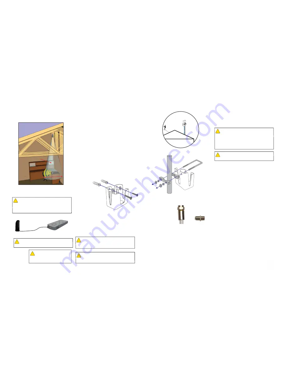
Rafter Mounting Option
1. Using the cradle as a template, position it on the
rafter in the desired location and mark the screw
holes with a pencil.
2. Drill two holes where marked, using a 3/16-inch
bit and insert the screw anchors.
3. Line up the holes in the cradle with the screw
anchors and mount the cradle to the wall using
two screws and two washers (see Figure
9). Tighten the screws with a Phillips-head
screwdriver.
4. Insert the antenna into the cradle
with the
Wilson insignia facing in the direction of
the cell tower.
The cable connection should
protrude through the bottom of the cradle.
5. Connect the supplied coax cable to the antenna.
Route the cable as desired to where the amplifi er
will be located. Depending on the distance
between the amplifi er and antenna, you may
need one or both lengths of the supplied cable.
If you use both, connect them together with the
supplied cable connector.
Figure 8-2
Null Zone
5 feet
NOTE: If you are planning on using the vertical
separation mounting options the desktop
antenna must be located at least 15 vertical
feet below the cradle antenna and within 5
horizontal feet of the cradle antenna. This
space is referred to as the Null Zone.
For Technical Support, call 866-294-1660 or 435-673-5021.
6
Outside Pole Mount (Packet A)
1. The supplied pole-mount bracket is designed to
accommodate a pole diameter of 1 to 2 inches.
Install the pole in the desired location using your
own hardware.
2. Insert the supplied U-bolt through the holes in the
cradle and slide one half of the bracket assembly
onto the U-bolt (see Figure 7).
3. Fitting the assembly onto the pole, slide the
second half of the bracket onto the U-bolt and
secure it with lock washers and nuts. Be sure
the cradle is at the desired height on the pole and
is rotated toward the nearest cell tower before
tightening the nuts. (Do not over-tighten the nuts.)
4. Insert the antenna into the cradle
with the
Wilson insignia facing in the direction of
the cell tower.
The cable connection should
protrude through the bottom of the cradle.
5. Connect the supplied coax cable to the antenna.
Route the cable as desired to where the amplifi er
will be located. Depending on the distance
between the amplifi er and antenna, you may
need one or both lengths of the supplied cable.
If you use both, connect them together with the
supplied cable connector.
Figure 7
Cell
Tower
Antenna
and
Cradle
Warning:
Take care to ensure that neither you nor the
pole comes near any power lines during installation.
!
Warning: RF Safety:
The cradle antenna, when used
with the included cable, must have a separation distance of
at least 8 inches from all persons. If the cable is shortened,
or if a different type of cable is used, or if a different antenna
is used, consult with Wilson Technical Support to verify that
the planned installation is safe. Call 866-294-1660 or 435-
673-5021, or email [email protected].
!
Installing the Cradle Antenna
Cable
Connector
Coax
Cable


