


Installation and electrical connection
en
Installation and operating instructions Wilo-Rexa UNI
17
ƒ
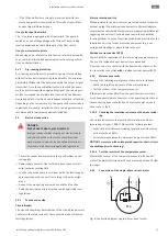
If the fill levels fluctuate strongly, a level control with two
measuring points is recommended. This makes it possible to
achieve larger differential gaps.
Use of attached float switch
The “A” version is equipped with a float switch. The pump is
switched on and off depending on the fill level. The switching
level is determined by the cable length of the float switch.
Use of on-site level controls
When using an on-site level control device, refer to the manufac-
turer’s own installation and operating instructions for specifica-
tions on the installation.
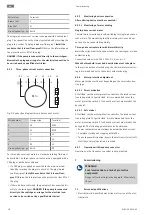
6.4.7
Dry-running protection
Dry-running protection must prevent the pump from operating
without fluid and air from entering the hydraulics. The minimum
permissible fill level must be determined with the help of a signal
transmitter. Once the specified limit value is reached, the pump
must be deactivated with an appropriate signal. Dry-running pro-
tection can expand the available level controls by an additional
measuring point or function as an independent switch-off device.
Depending on the system security, the pump can be restarted au-
tomatically or manually. Installation of dry-running protection is
recommended for optimum operational reliability.
6.5
Electrical connection
DANGER
Risk of death due to electrocution!
Improper conduct when carrying out electrical work
can lead to death due to electric shock! Electrical
work must be carried out by a qualified electrician in
accordance with the locally applicable regulations.
ƒ
The mains connection must match the specifications on the
rating plate.
ƒ
Power supply on mains side for three-phase current motors
with clockwise rotating field.
ƒ
Lay the connection cable in accordance with the locally applic-
able regulations and connect it according to the wire assign-
ment.
ƒ
Connect the monitoring devices and check their function.
ƒ
Earth the device properly in accordance with applicable local
regulations.
6.5.1
Fuse on mains side
Circuit breaker
The size and switching characteristics of the circuit breakers must
conform to the rated current of the connected product. Observe
local regulations.
Motor protection switch
Make provision for an on-site motor protection switch for devices
without a plug! The minimum requirement is a thermal relay/mo-
tor protection switch with temperature compensation, differential
triggering and anti-reactivation device in accordance with the
local regulations. In case of sensitive mains, make provision for the
installation on-site of other protective equipment (e.g. over-
voltage, undervoltage or phase failure relay, etc.).
Residual-current device (RCD)
Comply with the regulations of the local energy supply company!
The use of a residual-current device is recommended.
If persons come into contact with the device and conductive flu-
ids, secure the connection
with
a residual-current device (RCD).
6.5.2
Maintenance tasks
Carry out the following maintenance tasks prior to installation:
ƒ
Check the insulation resistance of the motor winding.
ƒ
Test the resistor of the temperature sensor.
If the measured values differ from the specifications, moisture
may have penetrated into the motor or the power supply cable or
the monitoring device is defective. Contact customer service in
the event of a fault.
6.5.2.1 Checking the insulation resistance of the motor wind-
ing
Use an insulation tester to measure the insulation resistance
(measuring voltage = 1000 V). Observe the following values:
ƒ
At the time of initial commissioning: Insulation resistance may
not be less than 20 MΩ.
ƒ
For further measurements: Value must be greater than 2 MΩ.
NOTICE! For motors with an integrated capacitor, short-circuit
the windings prior to checking!
6.5.2.2 Test the resistor of the temperature sensor
Measure the resistor of the temperature sensors with an ohm-
meter. The bimetallic strips must have a measured value of 0 Ohm
(passage).
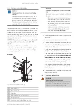
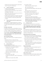
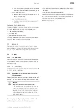
6.5.3
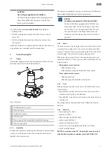
Connection of the single-phase current motor
U1/Z1
bn
U2 bu
Cr
M 1~
gn-y
e
L
N
PE
Fig. 8:
Connection diagram single-phase current motor


